Electronic components: Potentiometers
A potentiometer is a tiny component that has 3 connectors: 2 on one side, 1 on the other side:
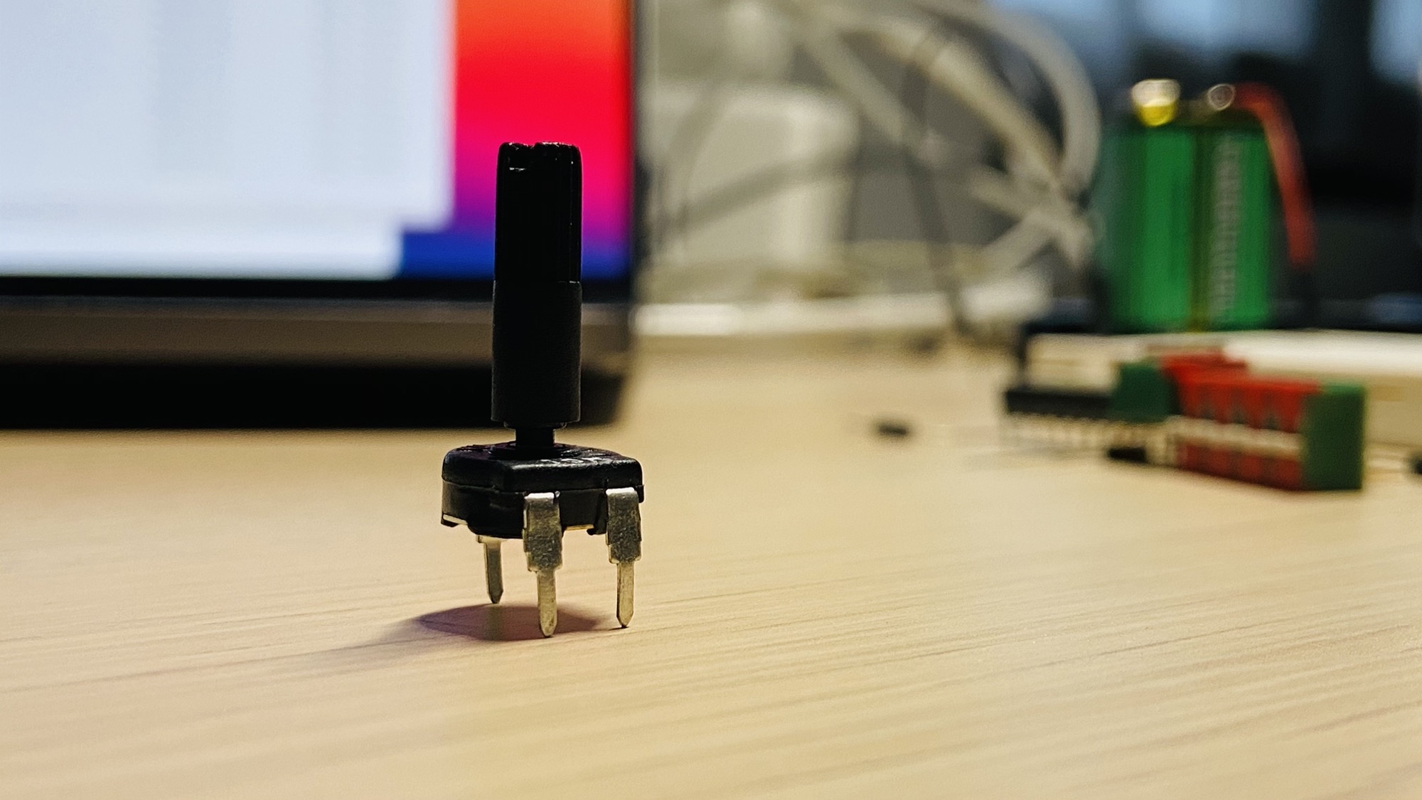
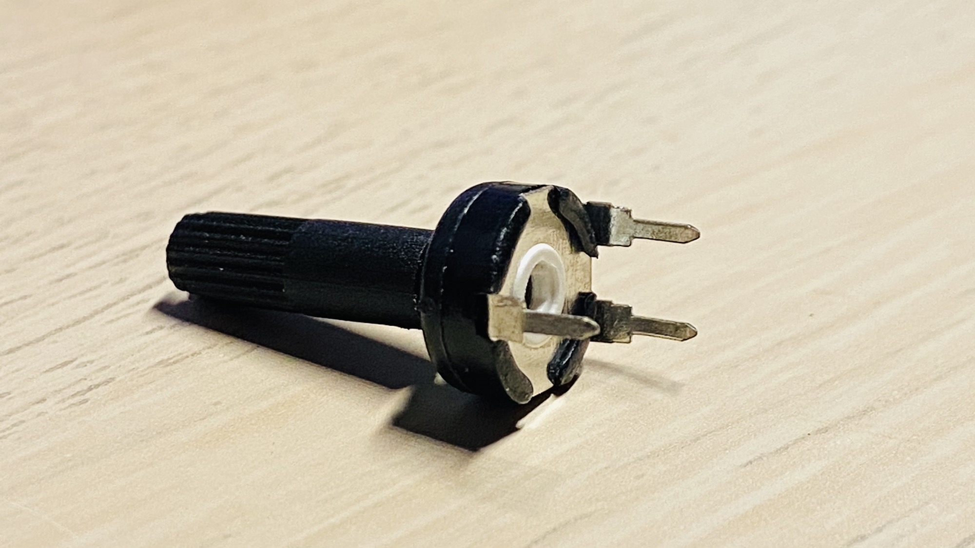
The two connectors are the input, they are connected to the negative and to the positive, and the opposite one is the output.
Rotating potentiometer we can have on output a fraction of the voltage difference we have in the input pins.
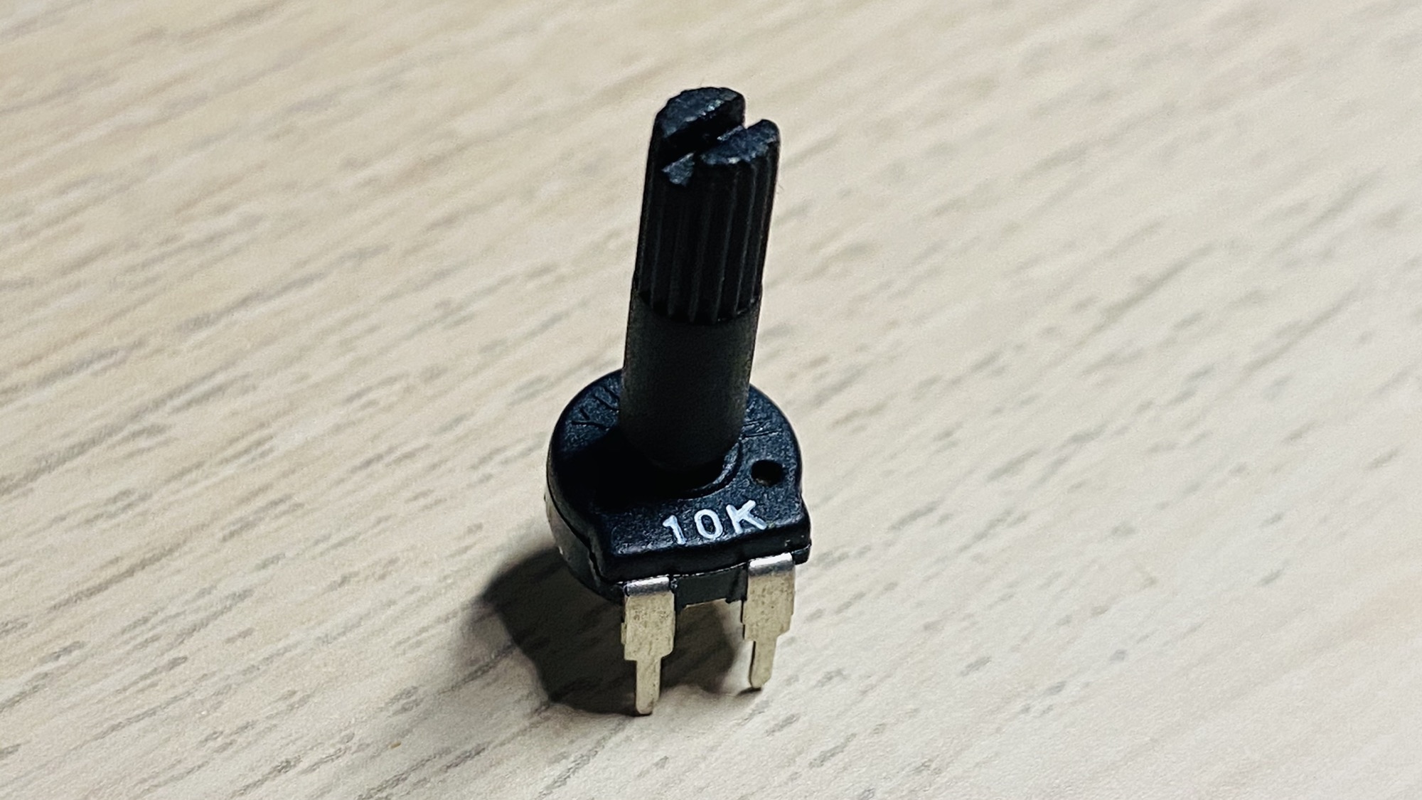
This is because the potentiometer is a resistor we can modify the resistance of. In this case I have a 10kΩ potentiometer:
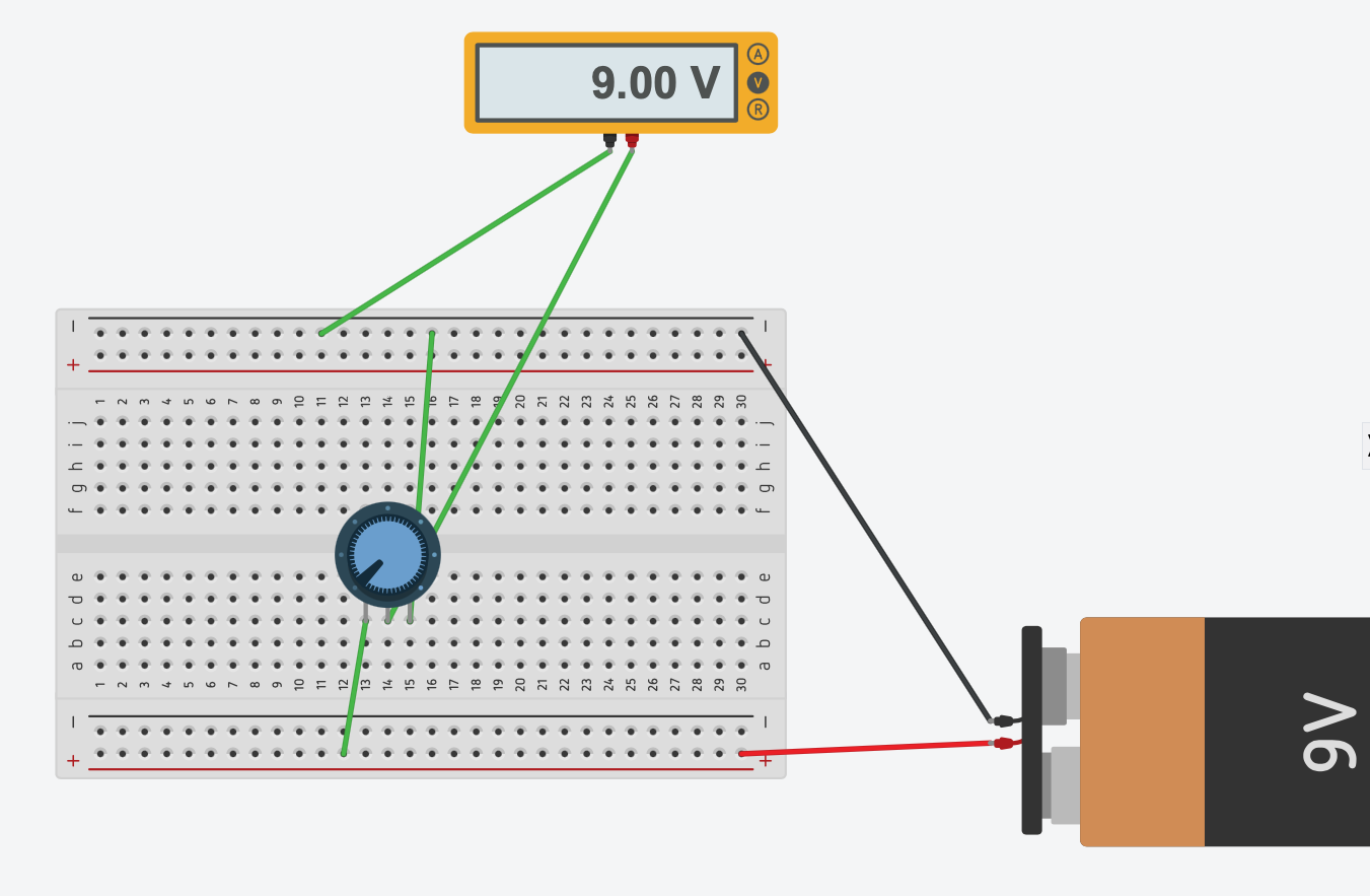
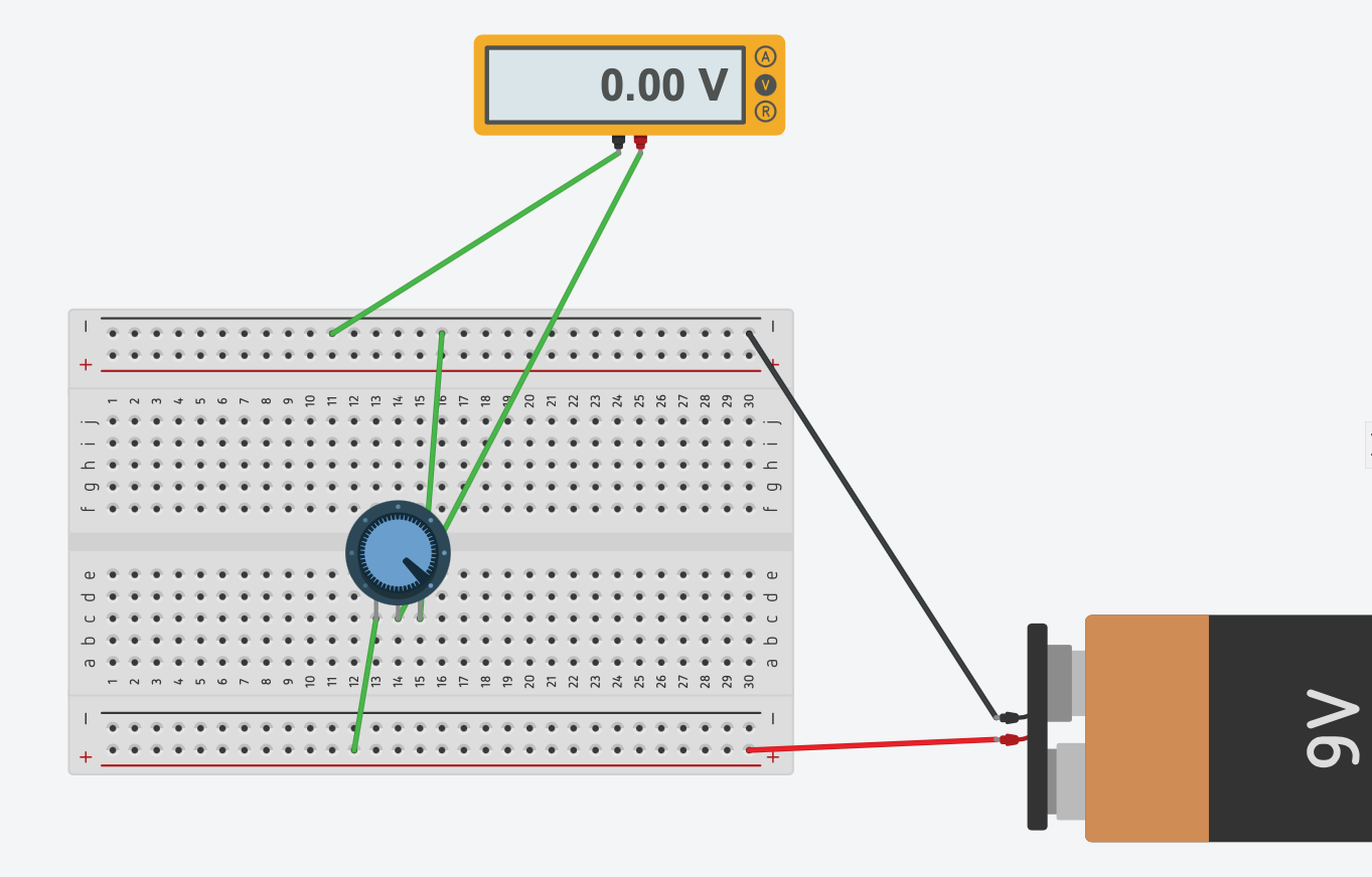
See this simulation: if we have the potentiometer at full left (counterclockwise), on the output pin we have a 9V difference between the output pin and ground, because the potentiometer is working at 100% as a 10kΩ resistance and absorbs all the current:
If we change the potentiometer value at full right, on the output pin we have 9V because the potentiometer does not absorb any current. It works like a wire, applying 0 resistance.
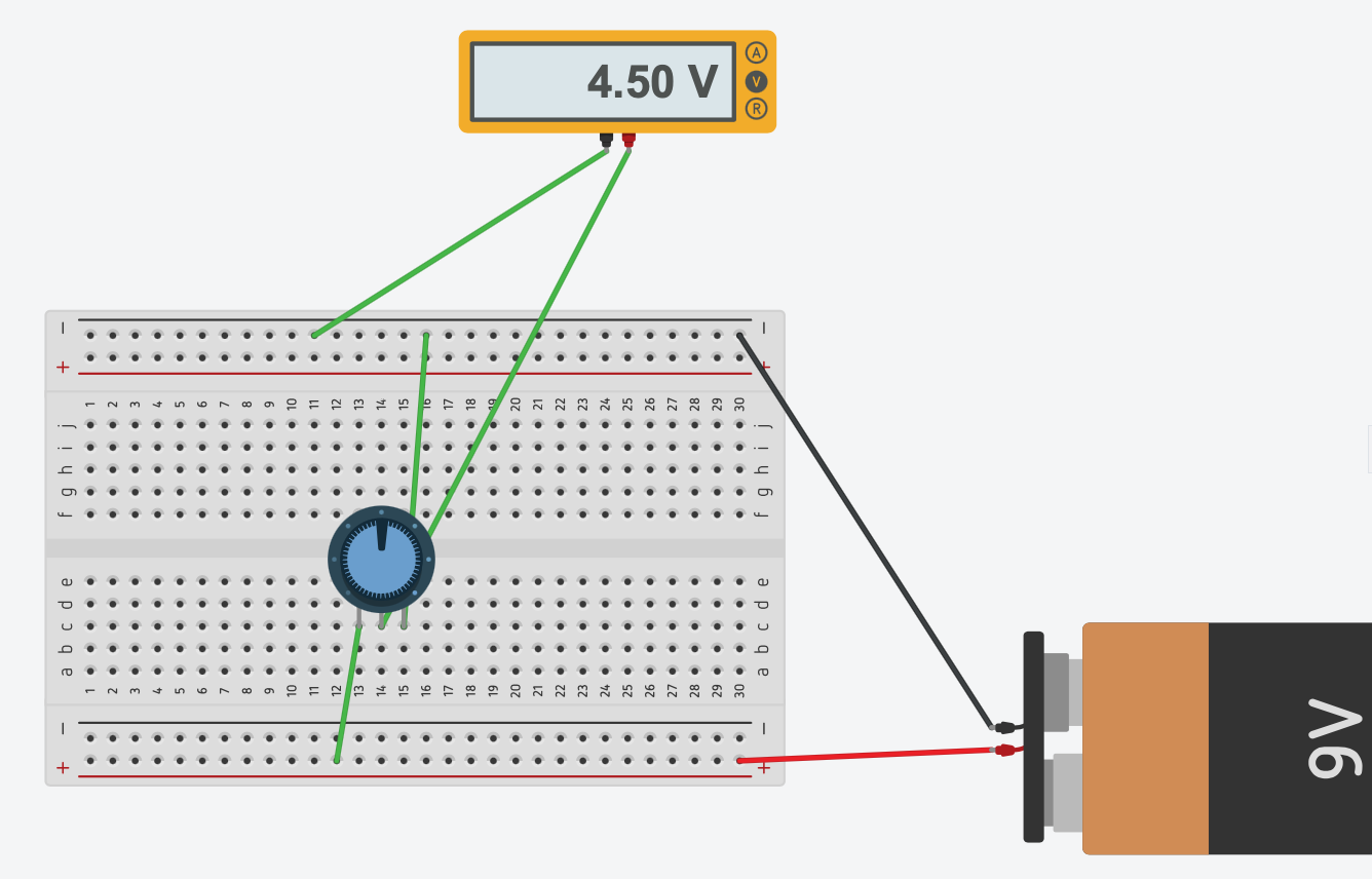
Having the potentiometer at 50% gives 1/2 of the starting tension in the output pin:
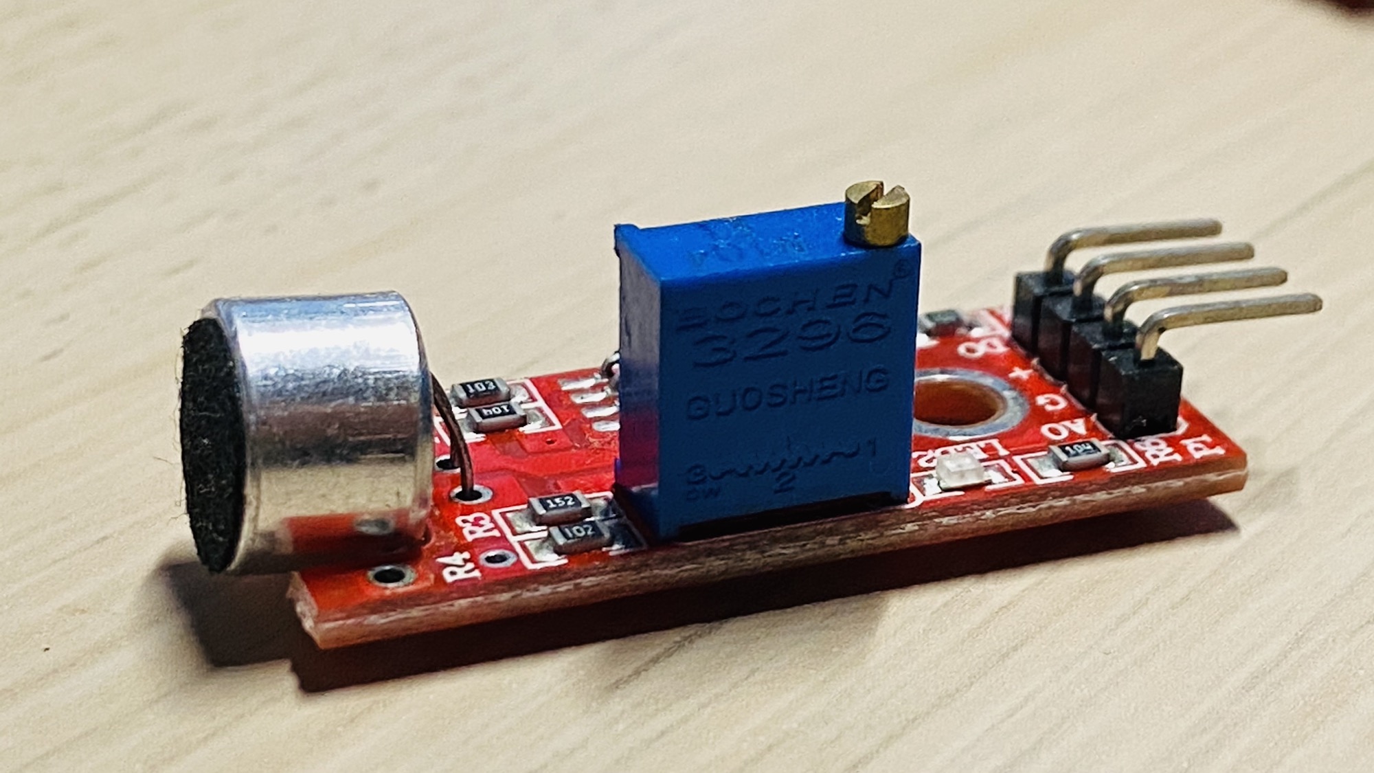
Potentiometer are handy for many reasons, on their own, but they are also used in integrated circuits to help us regulate the output, like in this case with a sound sensor where the potentiometer is the blue box we can regulate with a screwdriver:
Related posts about electronics: