Finite State Machines
A quick overview of what State Machines are, with simple examples
There’s a lot of talk about Finite State Machines these days in JavaScript land.
There’s this popular library called XState, with more than 11000 stars on GitHub, which I run into lately, and I keep reading about it on Twitter and other places. It’s a very cool project.
I have first met Finite State Machines and Automata back in High School, 20 years ago, then I met them again in my Digital Design course at the University.
This Digital Design course was about encoding information, boolean algebra, combinatorial networks, sequential circuits, sequential state machines, arithmetical circuits, VHDL, and more.
I found the topic of Finite State Machines applied to Frontend Engineering pretty amazing, and I went back to my old books to see if I could find a good explanation of them.
I did find a lot of information, and of course being textbooks things are made more complex than needed (IMHO). I like to simplify things, and I decided to write a little explanation for normal human beings, not theoretical or anything made to pass an exam. Things you can apply to the real world.
State Machines
Before looking into what a Finite State Machine is, I want to first introduce what a State Machine is.
The world is filled with state machines. You can see them everywhere, but perhaps you didn’t think of them as such. After reading this tutorial, I am sure you’ll point out objects in the real world saying to your friends “that’s a state machine” (depending on the nerdy level of your friends).
The most popular and commonly found example is traffic lights.
At any point in time, a traffic semaphore has a defined state. Typically, it either:
- has the green light on, and the other 2 lights off
- has the red light on, and the other 2 lights off
- as the yellow light on, and the other 2 lights off
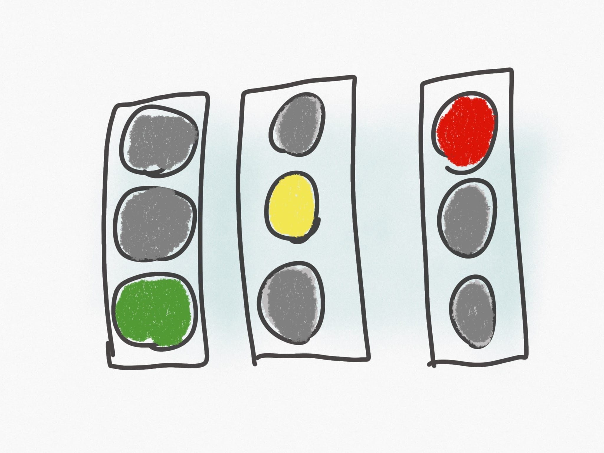
(Some semaphores are slightly different, but we don’t care for the sake of this example)
In State Machines terminology, lights being on or off is called output.
Each of those 3 scenarios is called state. The traffic semaphore will change state when it receives an input, typically just a fixed timer that decides how much time the traffic lights should be green, yellow and red.
The timer in this case is the input of the system. Some semaphores have a button that pedestrian can press to cause the red to display to cars, and that would be another input.
In a state machine, the state can only change (and we have a transition) in response to an input.
Finite State Machines
Our traffic lights state machine is said to be finite because we have a finite number of states.
Some systems might have an infinite number of states.
Like the world ecosystem model, or the life of an insect. We can’t define it in a finite number of states.
But traffic lights? That’s a simple thing, and it has 3 states, like we said above.
There are many more examples of finite state machines we could use:
- a vending machine
- a subway entrance turnstile
- a heating system
- an automated subway system
- a self-driving car system
- an elevator
But let’s stick to our traffic lights example, which is very simple and we can reason about it easily.
Modeling a State Machine
Of course traffic lights do not exist in isolation. That’s another finite state machine, which contains multiple different finite state machines for each traffic lights device installed for each side of each road of an intersection, which work in sync.
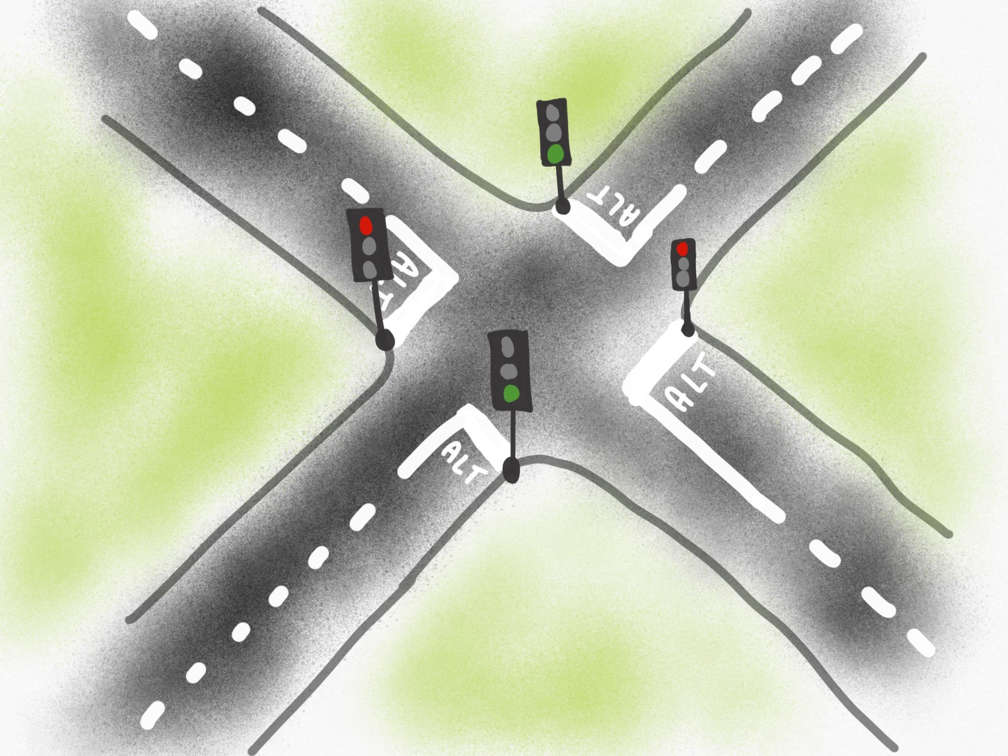
Don’t think about it now. Let’s focus on 1 single traffic semaphore.
As we said above, we have 3 states, which can call green, red, yellow.
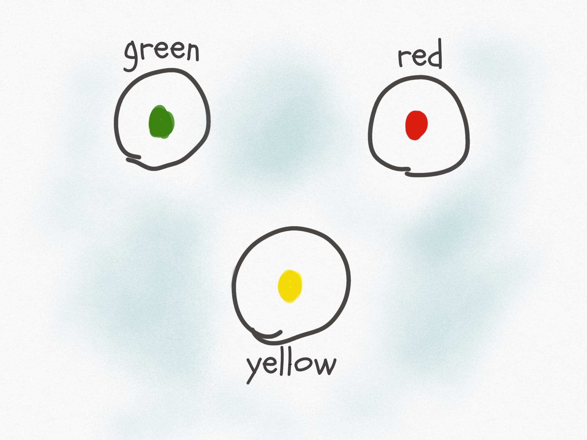
We have an initial state. Let’s say our traffic lights start, when we reset them, at the green state.
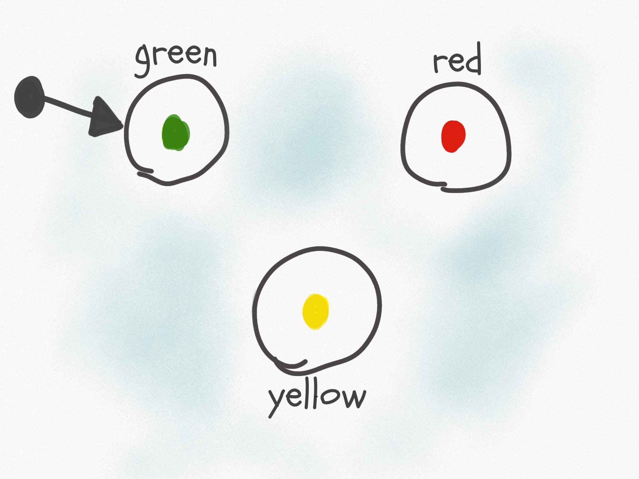
We have a timer that after 50 seconds of green state, moves the semaphore into the yellow state. We have 8 seconds of yellow state, then we move to the red state, and we sit there for 32 seconds, because that road is secondary and it deserves less time of green. After this, the semaphore gets back to the green state and the cycle continues indefinitely, until the electricity halts and the semaphore resets when it gets the power again.
In total, we have a 90 seconds cycle.
This is how we can model it:

We can also model it with a state transition table, which shows the state the machine is currently in, what is the input it receives, what is the next state, and the output:
| State | Input | Next state | Output |
|---|---|---|---|
| Green | Timer 50s | Yellow | Green light on, others off |
| Yellow | Timer 8s | Red | Yellow light on, others off |
| Red | Timer 32s | Green | Red light on, others off |
In our simple case, given any state of the machine we just have one logical state to go to, so the table and the chart I made are very, very simple.
But when your system starts to get more complex, it’s very helpful to have such diagrams and analysis in place because you can reason about your application much easier than by simply keeping everything in your head.
A Finite State Machine with more complex State Transitions
The above example is very simple. Let’s model another Finite State Machine now.
Our real world scenario is this: we have a house, with one door, 2 buttons and 3 lights.
At the default state the lights are all turned off.
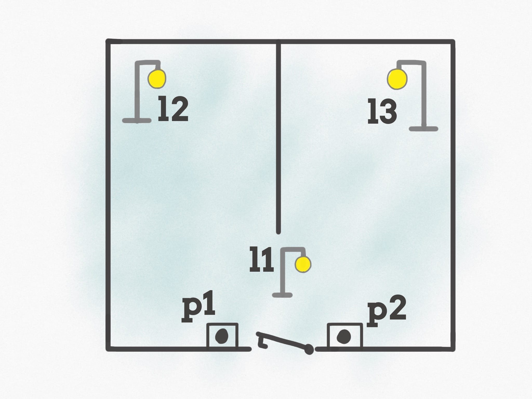
When you enter the house, you can press one of the 2 push buttons you have, p1 or p2. When you press any of those buttons, the l1 light turns on.
Imagine this is the entrance light, and you can take your jacket off. Once you are done, you decide which room you want to go into (kitchen or bedroom, for example).
If you press the button p1, l1 turns off and l2 turns on. Instead if you press the button p2, l1 turns off and l3 turns on.
Pressing another time any of the 2 buttons, p1 or p2, the light that is currently on will turn off, and we’ll get back at the initial state of the system.
This Finite State Machine is slightly more complex than the first, because this time we can have multiple routes depending on the input.
Let’s model this.
We basically have 4 states:
- no lights turned on
l1turned onl2turned onl3turned on
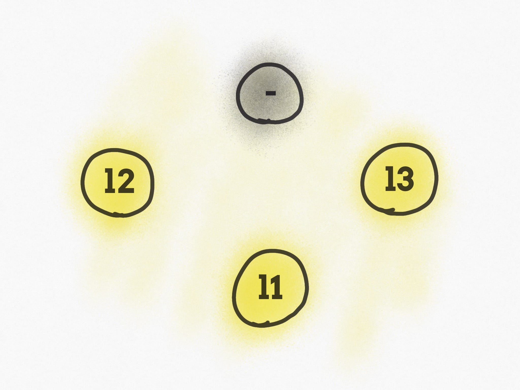
We have 2 inputs:
p1p2
If we start from the initial state, and we try to model everything that can happen depending on how the inputs are triggered over time, we end up with:
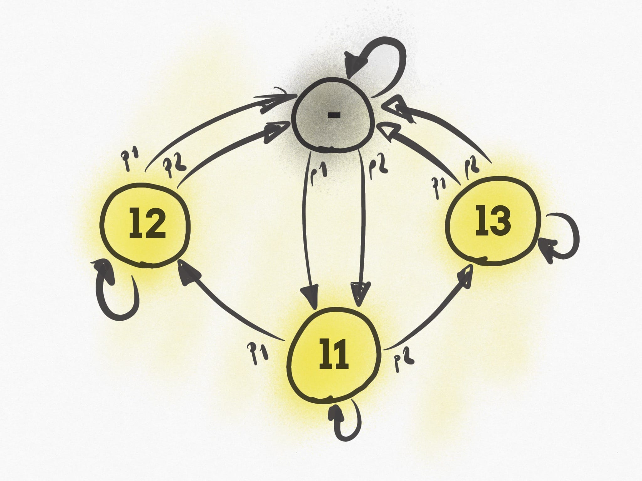
Which can be summarized using this table:
| State | Input | Next state |
|---|---|---|
| no lights turned on | p1 pressed | l1 turned on |
| no lights turned on | p2 pressed | l1 turned on |
l1 turned on | p1 pressed | l2 turned on |
l1 turned on | p2 pressed | l3 turned on |
l2 turned on | p1 pressed | no lights turned on |
l2 turned on | p2 pressed | no lights turned on |
l3 turned on | p1 pressed | no lights turned on |
l3 turned on | p2 pressed | no lights turned on |
That’s a short and simple explanation, but maybe it makes things “click”.
→ I wrote 17 books to help you become a better developer:
- C Handbook
- Command Line Handbook
- CSS Handbook
- Express Handbook
- Git Cheat Sheet
- Go Handbook
- HTML Handbook
- JS Handbook
- Laravel Handbook
- Next.js Handbook
- Node.js Handbook
- PHP Handbook
- Python Handbook
- React Handbook
- SQL Handbook
- Svelte Handbook
- Swift Handbook
Also, JOIN MY CODING BOOTCAMP, an amazing cohort course that will be a huge step up in your coding career - covering React, Next.js - next edition February 2025