Measuring voltage, current and resistance using a multimeter
By Flavio Copes
Learn how to measure voltage, resistance, and current with a digital multimeter, including why current must be read in series while the rest go in parallel.
A digital multimeter is a handy tool, one of the few tools you’ll need to start with.
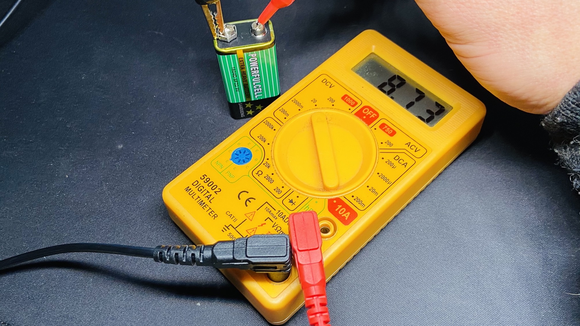
There are many kinds of multimeters, from very cheap ones (~10$) like this which was very cheap to buy but also has a very cheap feeling:
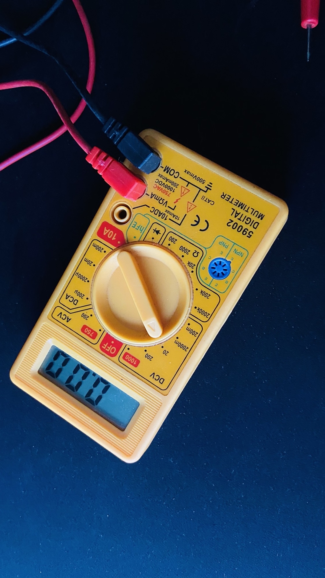
Unless you go on a very professional line, which you don’t need to start with, you can get a great one for < 30$.
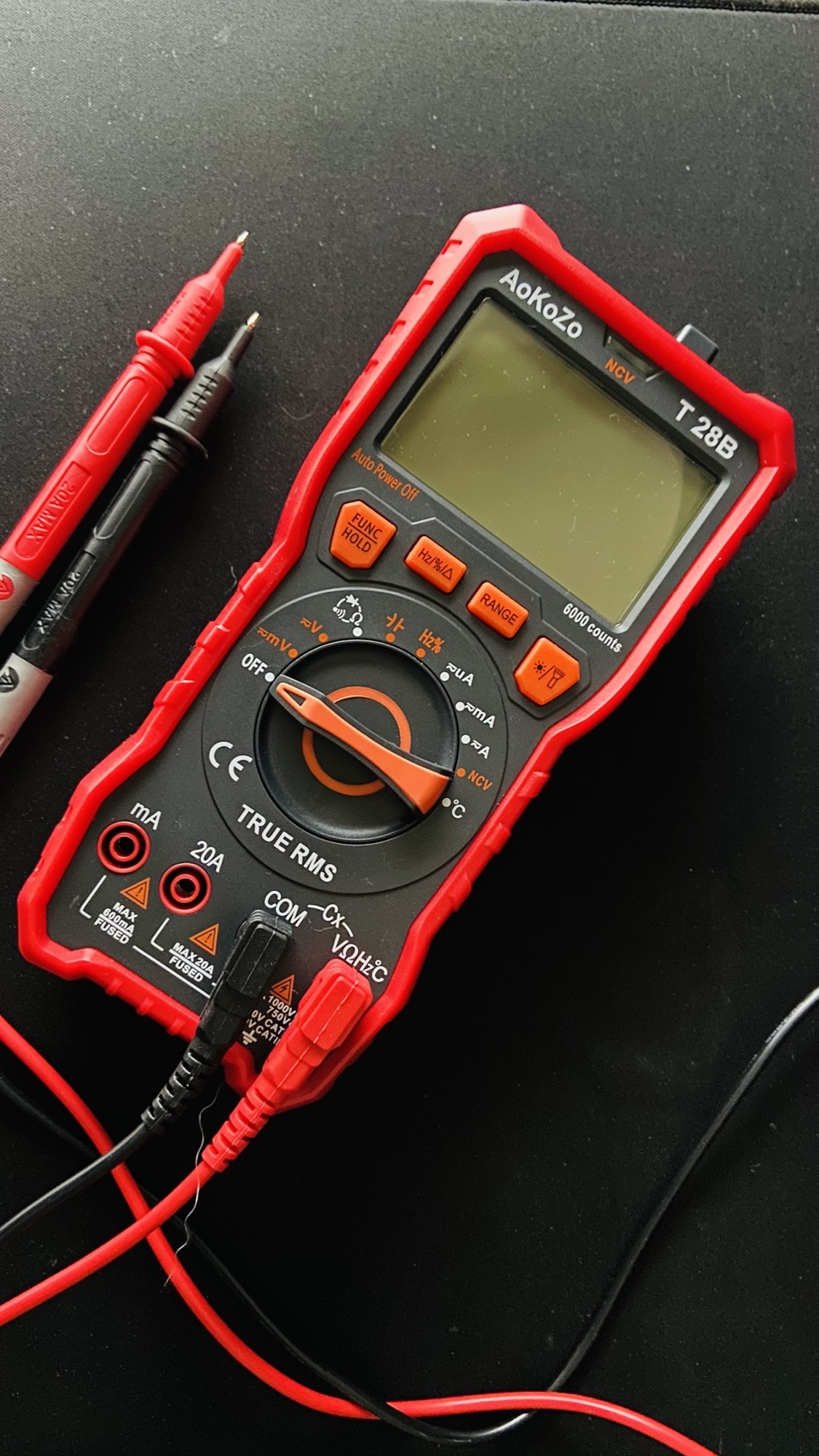
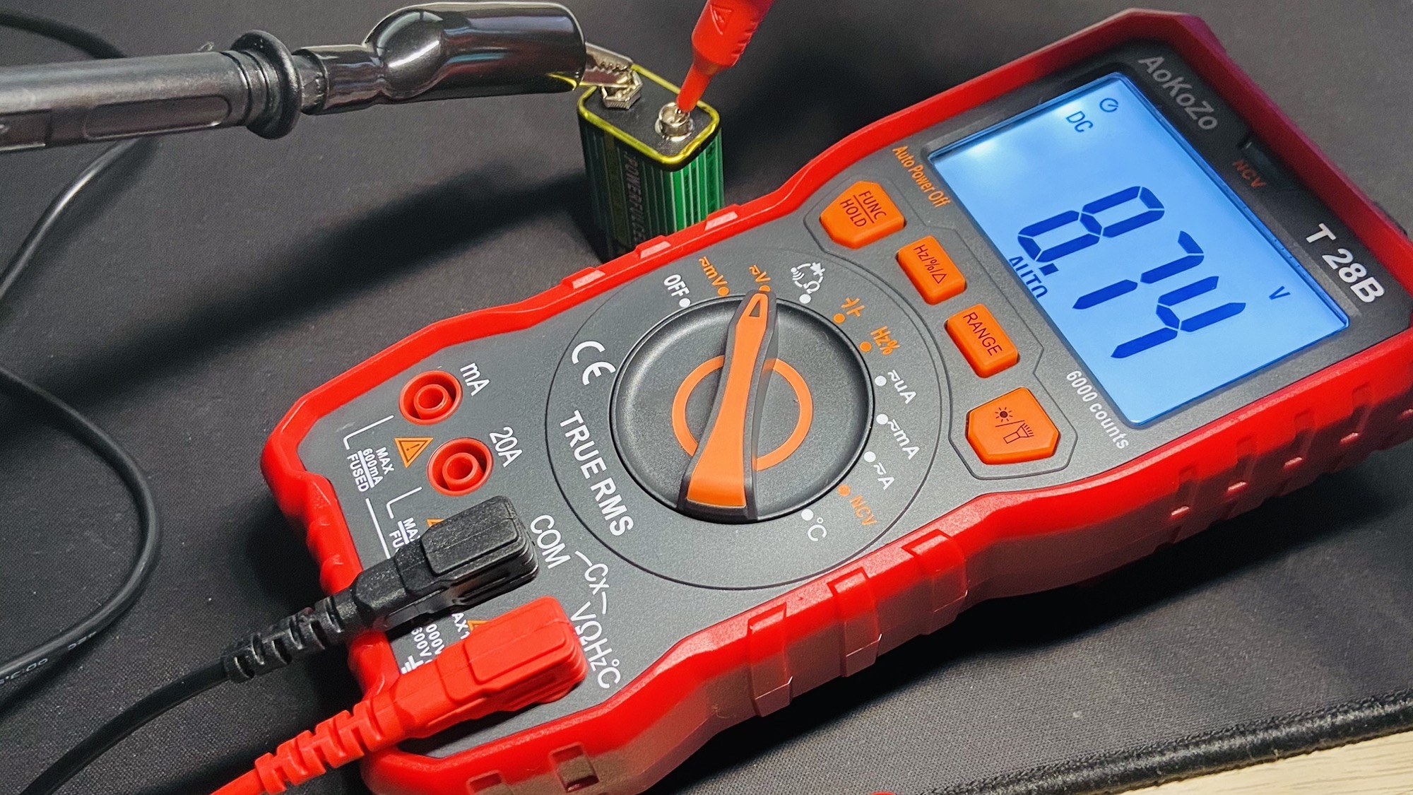
I paid this 30$ and it’s very well made:
Between those 2 there’s a big difference in size and build quality:
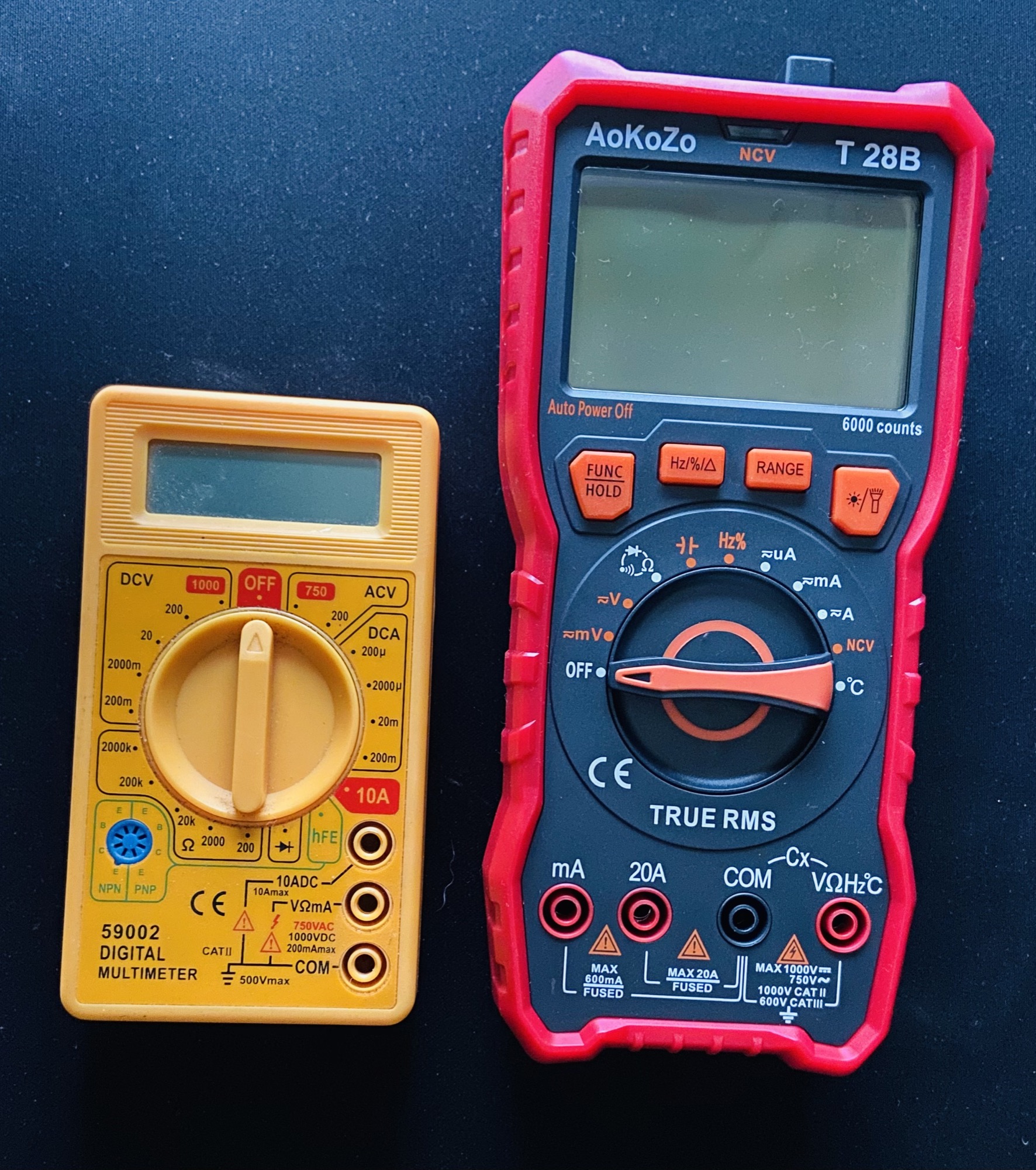
You can also see one has a 10A port, and the other has a 20A port. This means one can measure up to 20 Ampere of current before breaking its fuse, the other half of that.
The mA port can measure up to 500mA in the bigger one, 200mA in the smaller.
Also, one can measure temperature as well with a special cable. It has a light, and so on.
A digital multimeter can measure voltage (voltmeter), current (ammeter), resistance (ohmmeter), capacity, frequency, and more.
It’s a lot of tools built into one.
I’ll show you how to measure the first 3 things.
How to measure voltage
Let’s start by measuring voltage. Take a battery, connect select the V symbol:
and connect the black connector to COM, the common ground, and red connector to the V symbol, then connect the other end of the cables to the + and - battery terminals:
How to measure resistance
Now let’s see how to measure resistance.
Connect the two cables to the two ends of a resistance, and select the Ω symbol on the multimeter:
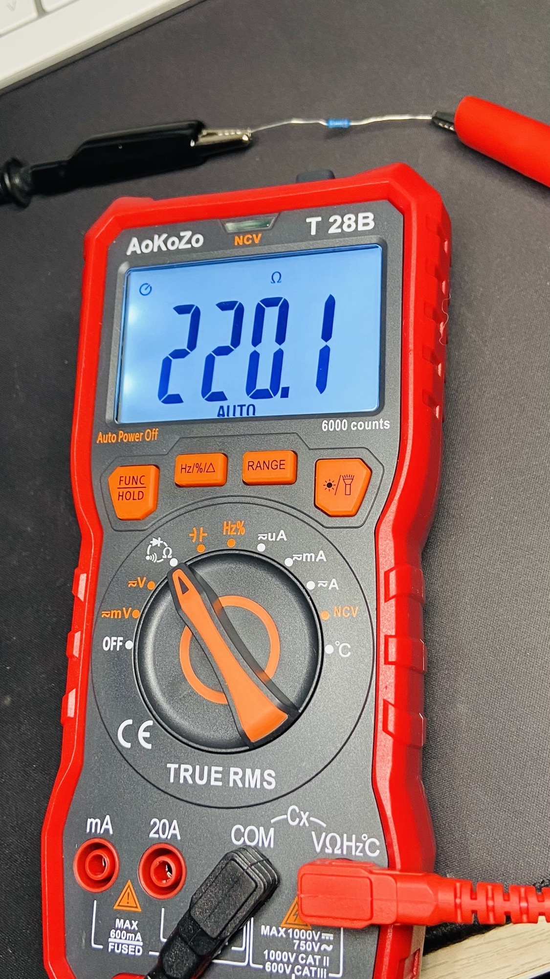
It’s a 220Ω resistance.
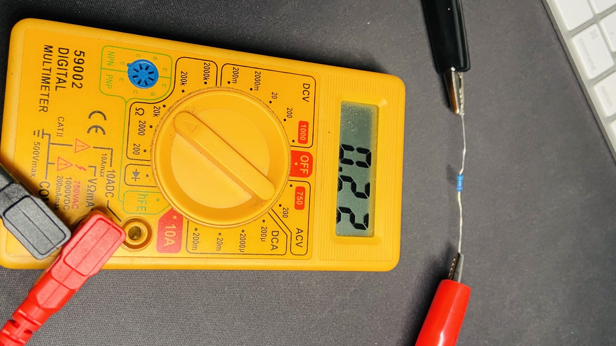
Here’s the same measurement on the cheaper multimeter:
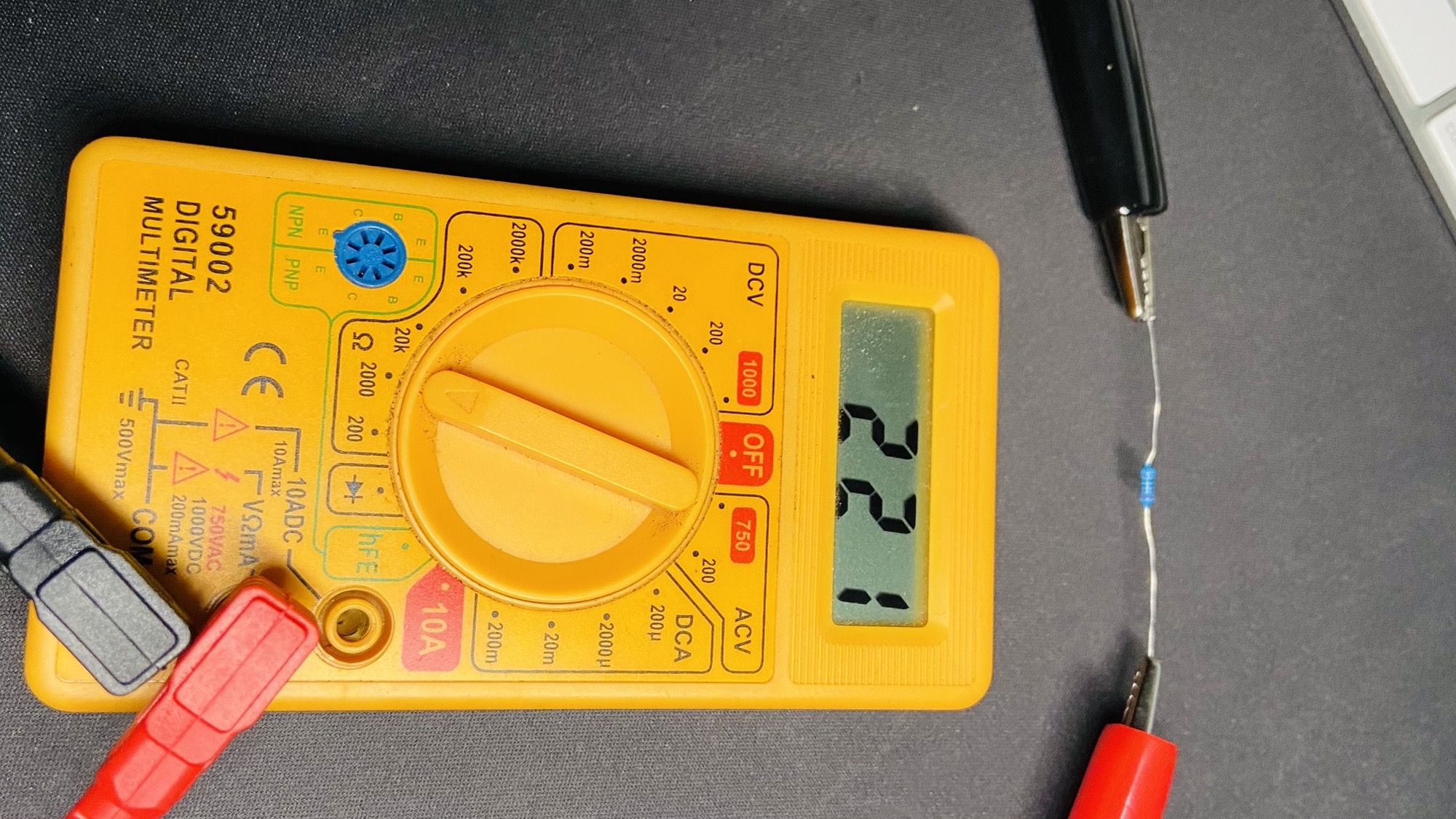
Notice that previously we didn’t have to set the scale, it was automatically determined. Here if the resistance is too low or too high for the scale you need to tweak it between the 200 2000 20k 200k 2000k points to see which one gives you a meaningful result.
For example here I picked the 20k scale, and I got 0.22 in the display. 20k means it can measure up to 20kΩ. 0.22 in this case means it’s 0.22 of 1kΩ:
Slightly confusing, right? It’s not optimal, so I recommend you pick a multimeter that can determine the scale automatically.
How to measure current
I showed you how to measure voltage and resistance first, because they work in a similar way: the connectors are put in parallel to the item we want to measure.
Measuring current is different. We need to put the multimeter in series, making current flow through it.
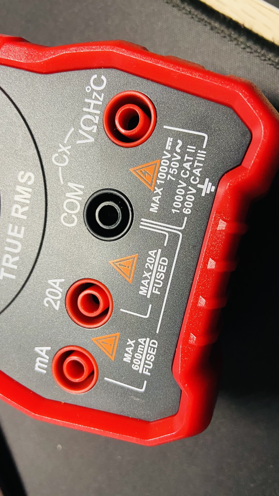
Also, depending on your multimeter, you might need to change the entry point for the cable. In this case I measure volts and Ω using the input #4, but current is measured using input #1 (and high amounts of current through input #2):
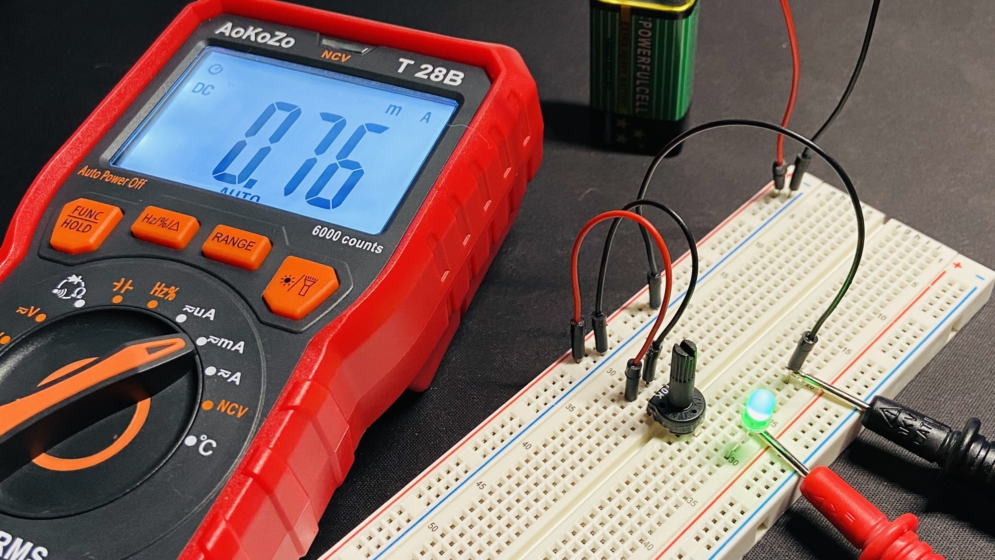
To measure current let’s build a little circuit. In this case I have a potentiometer that lights a LED.
The two cables connect the LED cathode to the lead that closes the circuit to GND. This is important: you don’t measure the current flowing through an element by connecting the multimeter to its cables directly. You need to make the multimeter part of the circuit.
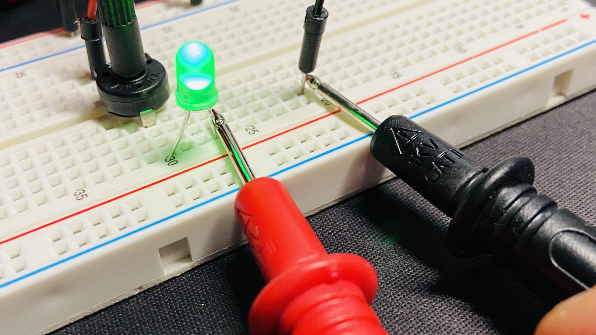
The multimeter acts as a wire.
On the multimeter you can choose the scale for the current measurement. We set it to mA, but try switching to uA to measure it in microamperes instead of milliamperes:
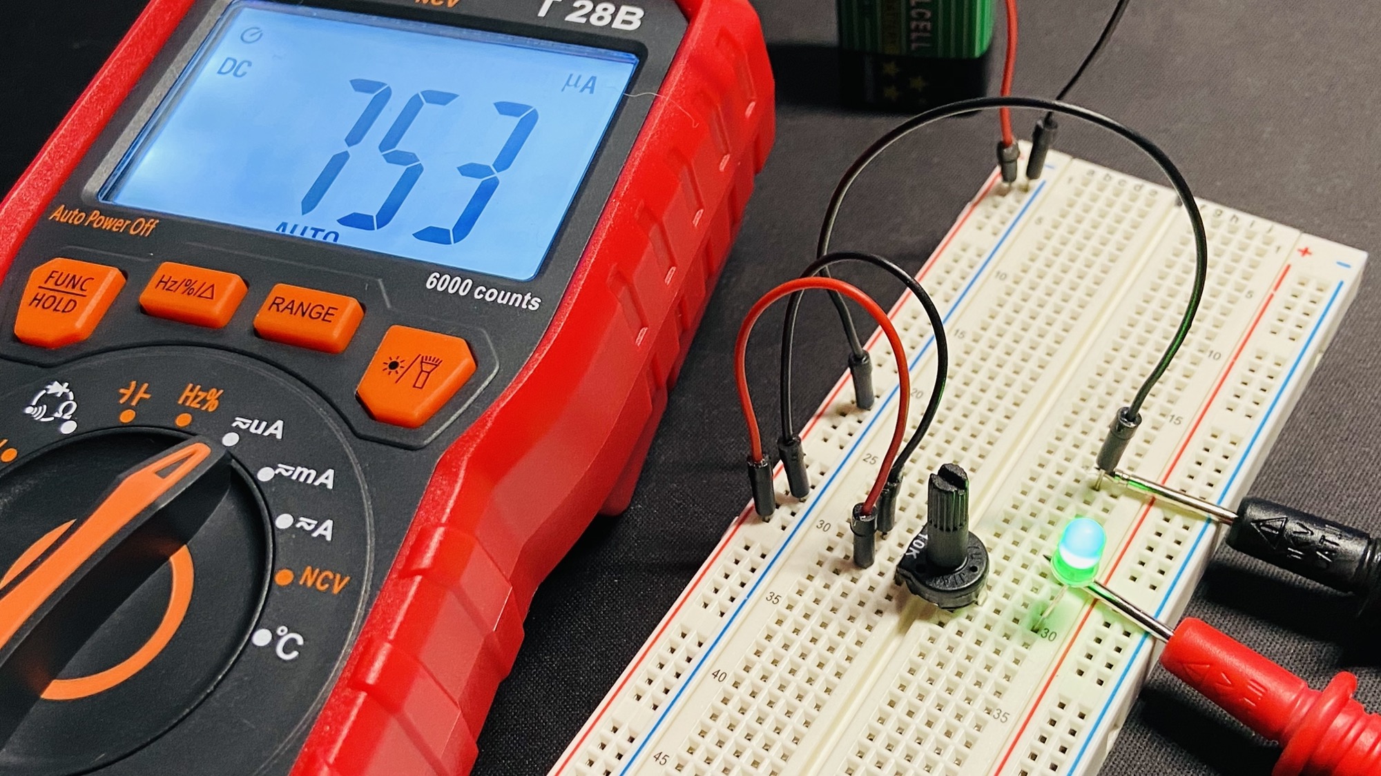
You got 753uA, which are equal to 0.753mA.
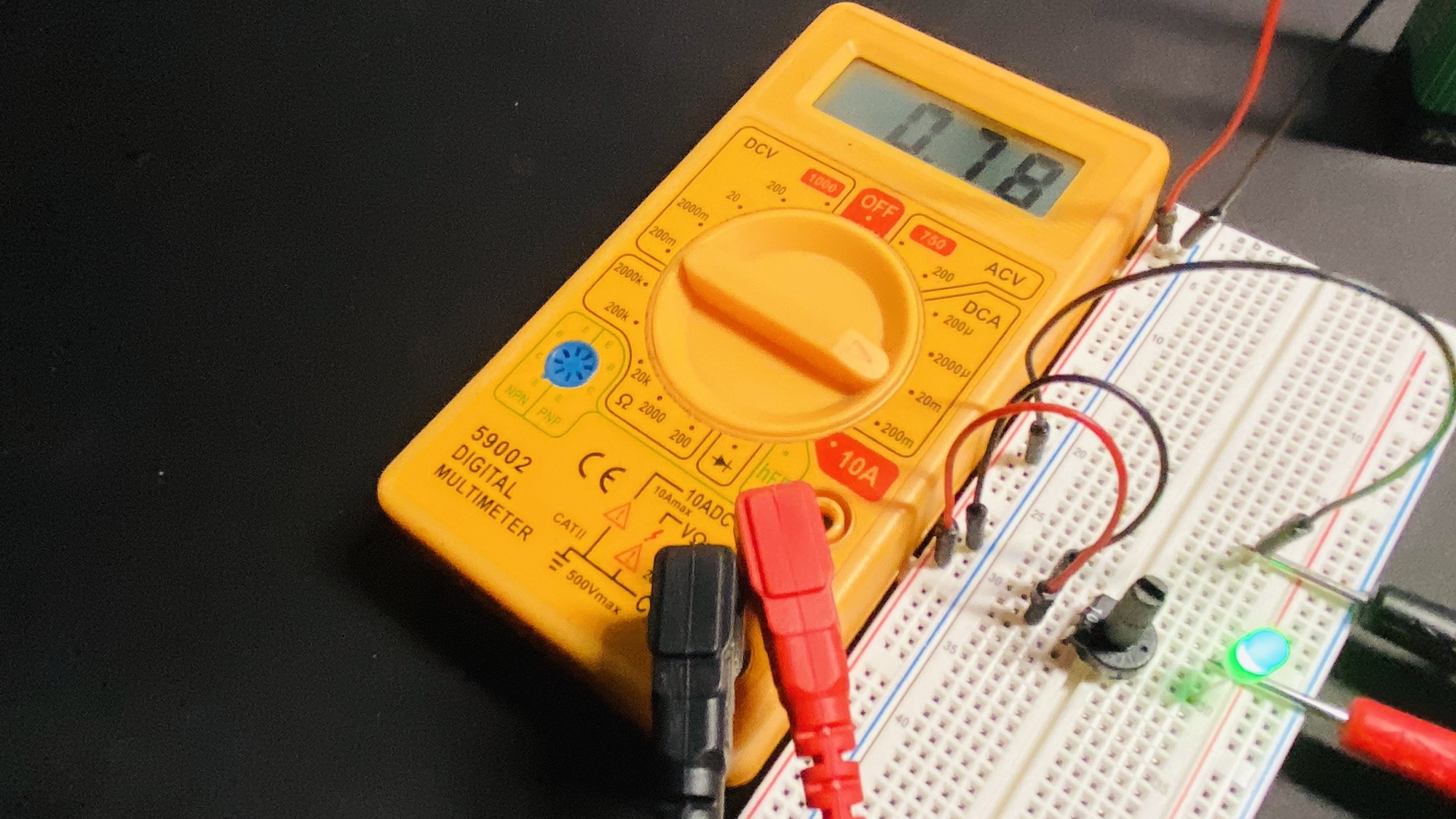
Here’s the same measurement using the yellow multimeter, in this case the port to measure small currents is the same as the one we used for voltage and resistance:
Related posts about electronics: