Electronics Basics: Prototyping using breadboards
By Flavio Copes
An introduction to breadboards for electronics prototyping: how the rows of holes connect under the surface, how the power rails work, and when to solder.
In this image you can see a simple circuit with a battery, a resistor and a LED.
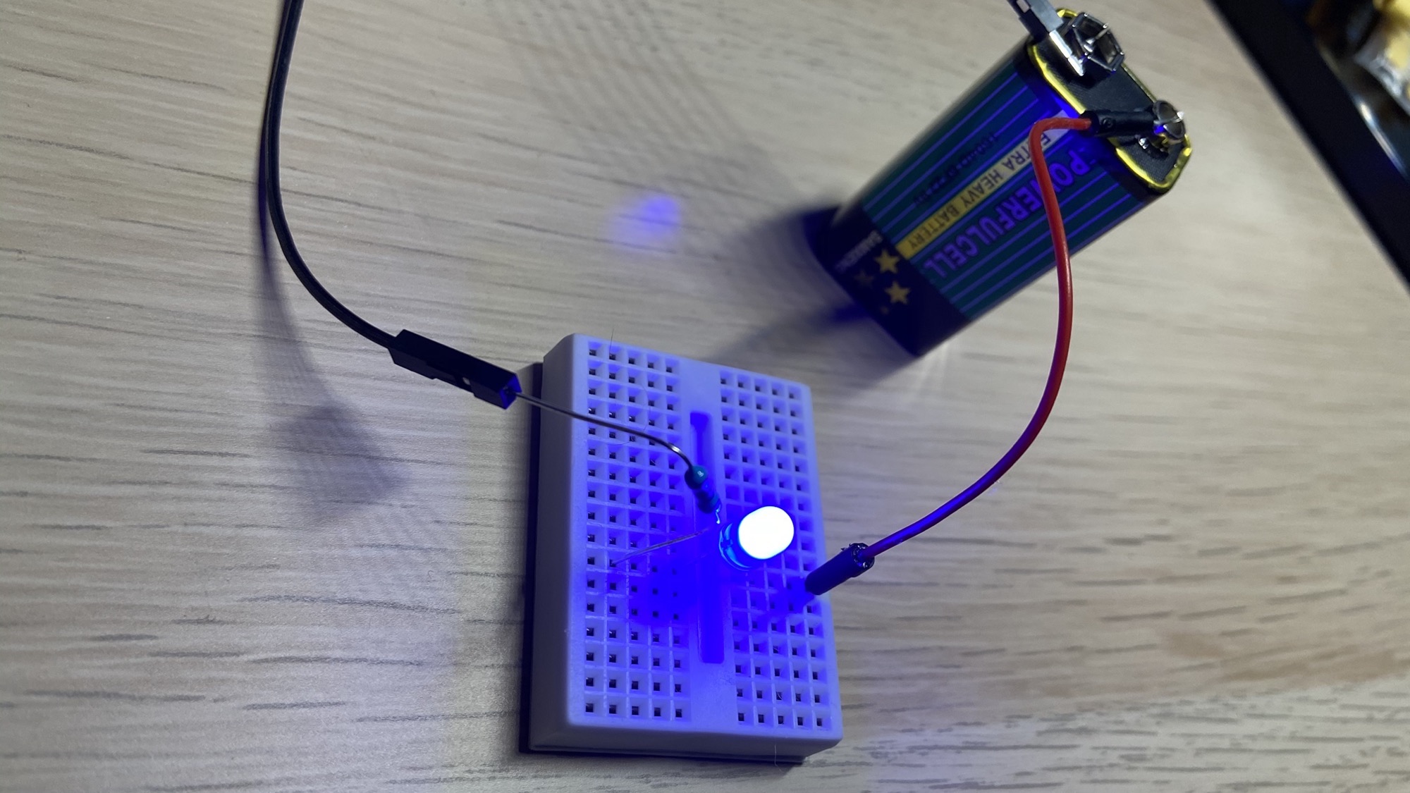
The elements are displayed inside a tiny white box called breadboard:
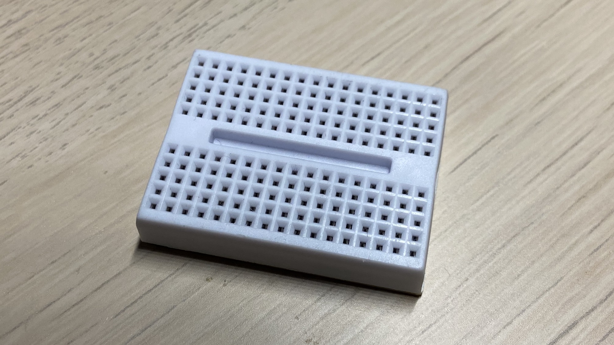
The breadboard has 17 sets of 5 interconnected elements on one side, and 17 sets of interconnected elements on another side.
Under the surface, the 5 holes in a set are connected with each other, so we can easily create electric connections.
This is a tiny board useful for simple prototyping.
This is a bigger board:
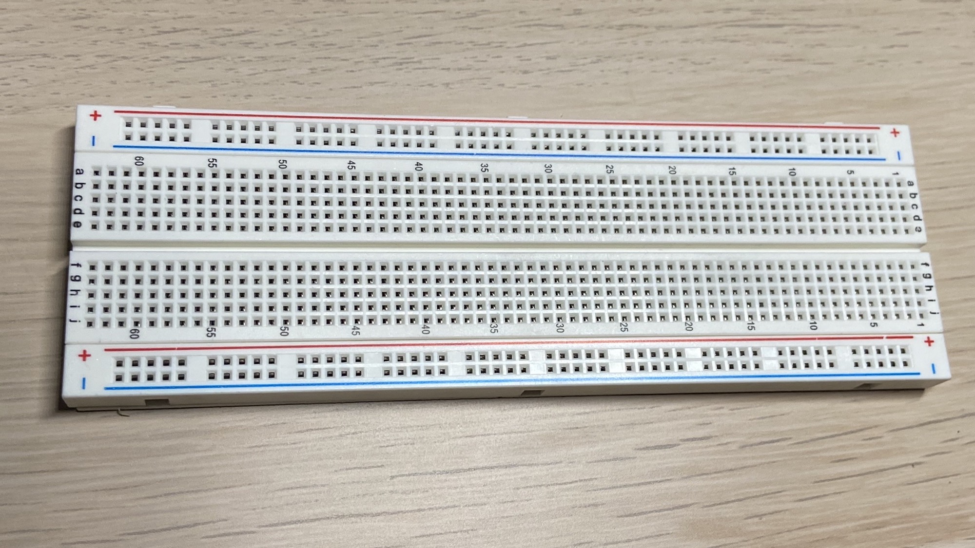
The principle is the same, and we have more elements on the outer border, the ones wrapped inside the red and blue lines:
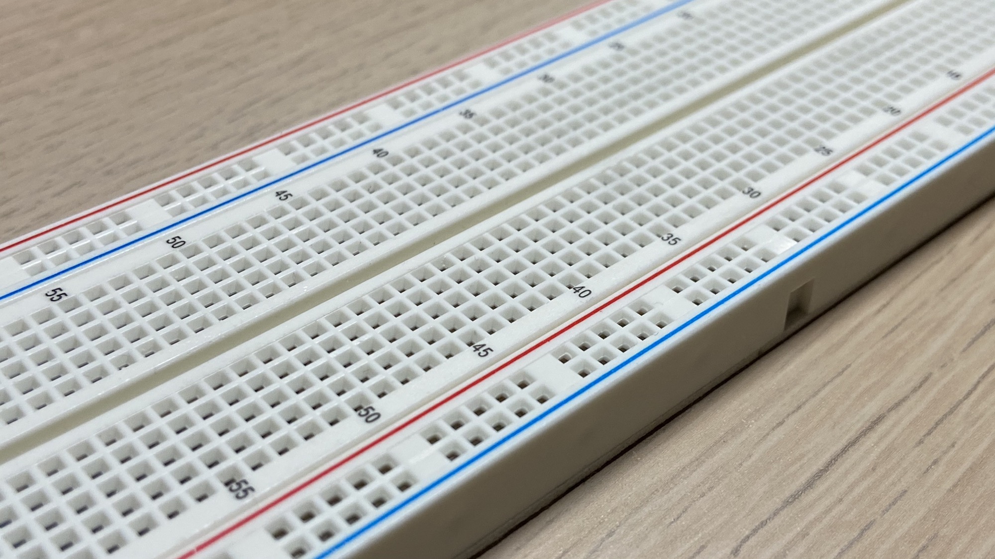
In this case the items are connected longitudinally, orthogonally to the 5-elements sets in the inside of the board:
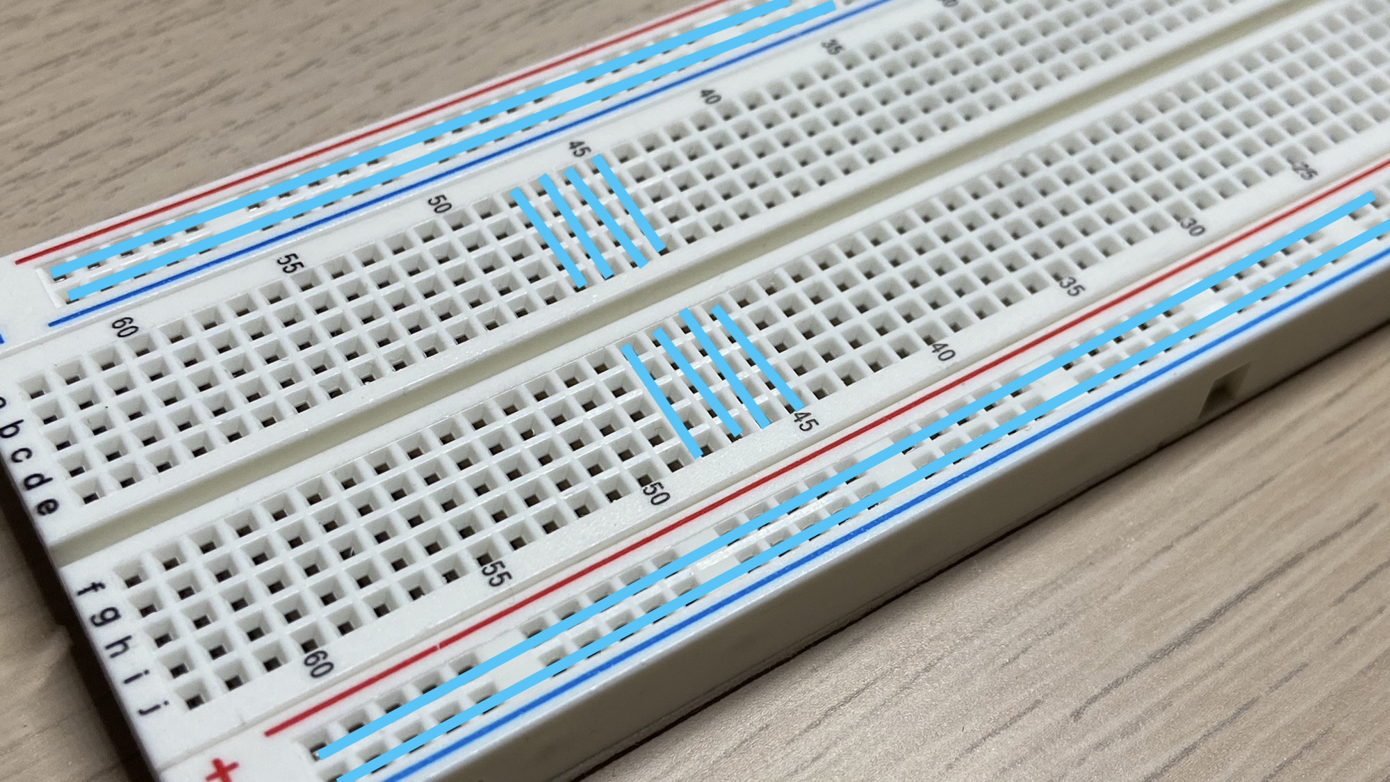
They are used to connect the positive and negative poles of the battery (or any other power source) to the board, so your elements on the board have easy access to them.
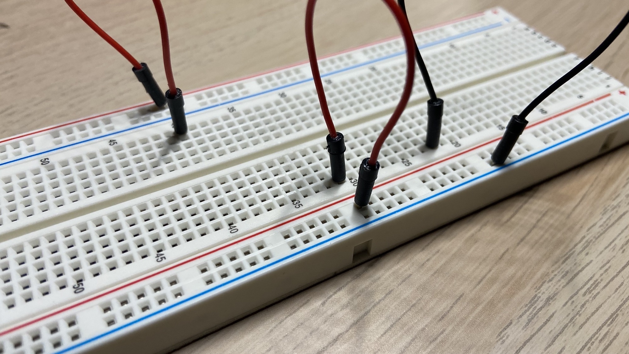
It’s common to use red wires for the + positive pole and black wires for the - negative pole:
You typically prototype a circuit using a breadboard:
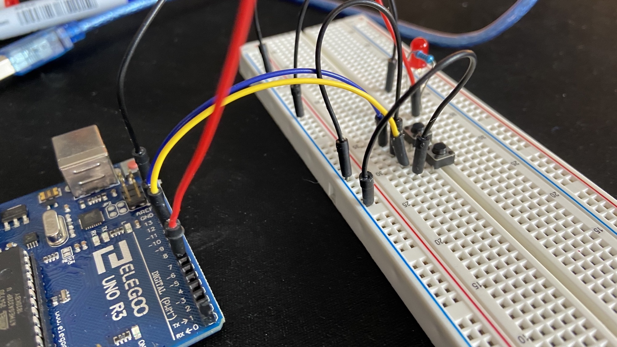
and once you’re ready to move on you can solder it into a perforated board.
Related posts about electronics: