Electronics Basics: Your first circuit
By Flavio Copes
Build your first electronics circuit to light a LED with a battery and resistor, simulate it for free in Tinkercad, and see Ohm's law set how bright it glows.
One of the simplest correctly-working circuits we can build is a circuit to light a LED.
We will use a 9V battery, a 470 ohm resistor, and a LED.
We’ll talk about resistors and LEDs in more details later, but let’s now create our first circuit.
You don’t need to buy any gear or components, if you don’t want, but I highly recommend you to do so, and to get a starter kit from Elegoo called “ELEGOO UNO R3 Project Most Complete Starter Kit”. You can find it on Amazon.
There are many online tools you can use to simulate a circuit. In this post we’re going to use Tinkercad, available for free use at https://tinkercad.com.

Tinkercad, from Autodesk, the creators of the famous AutoCAD, lets you create and simulate electronic circuits, but not just that - you can also create designs for 3D printing. It’s a very cool web application.
Create a free account on the site, then from the dashboard choose the Circuits menu:

Click the Create new Circuit button, and you’ll see the circuit builder interface:
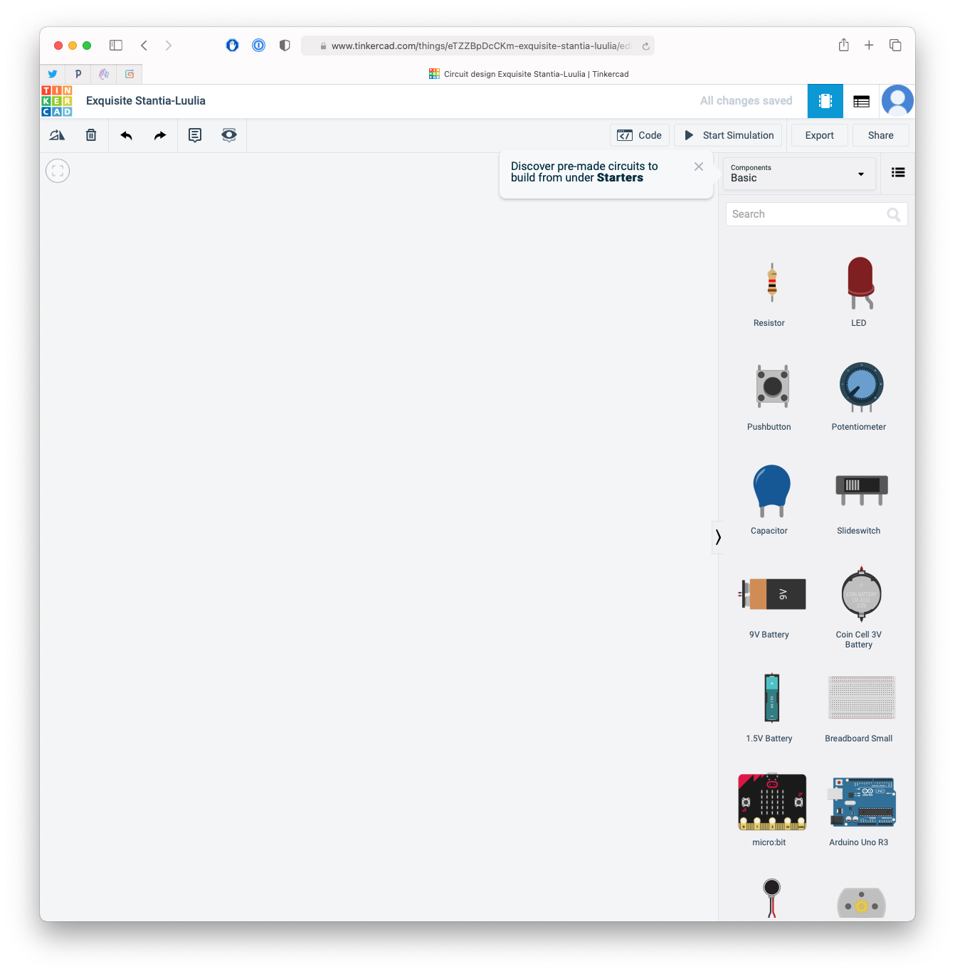
Now you can drag and drop components from the right sidebar on the main screen.
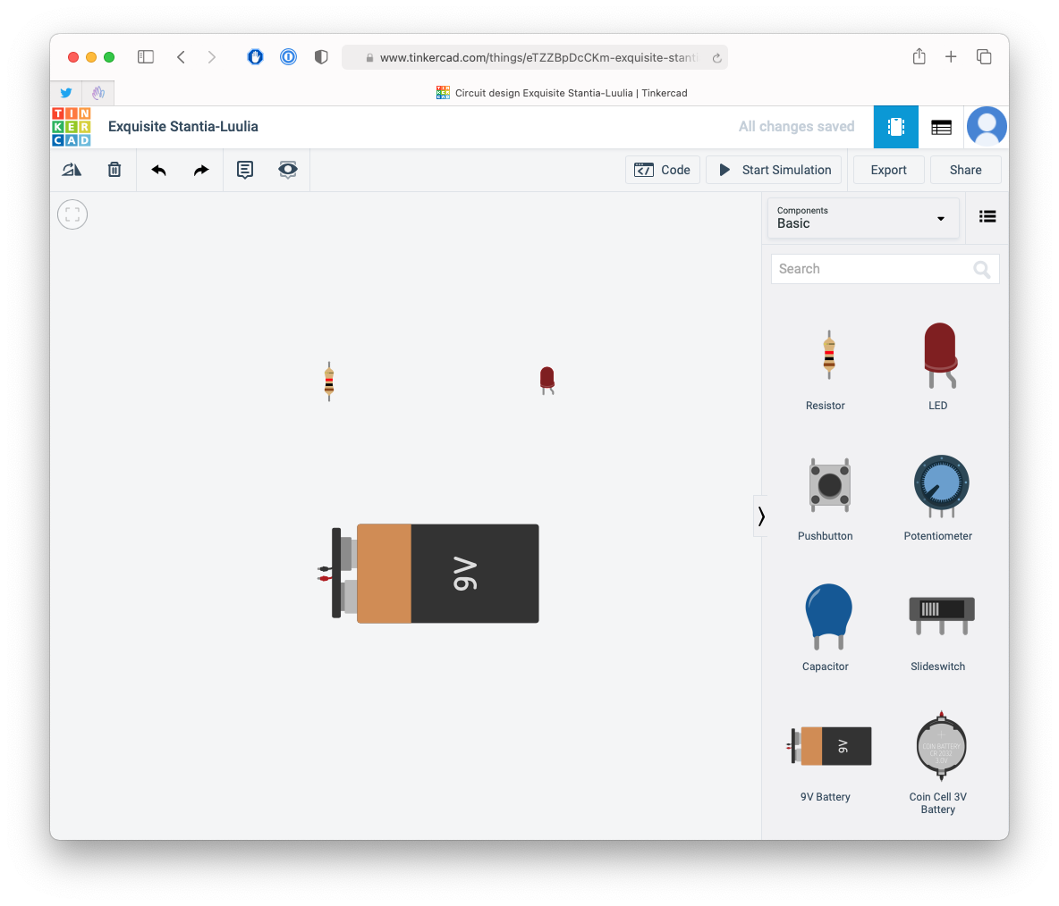
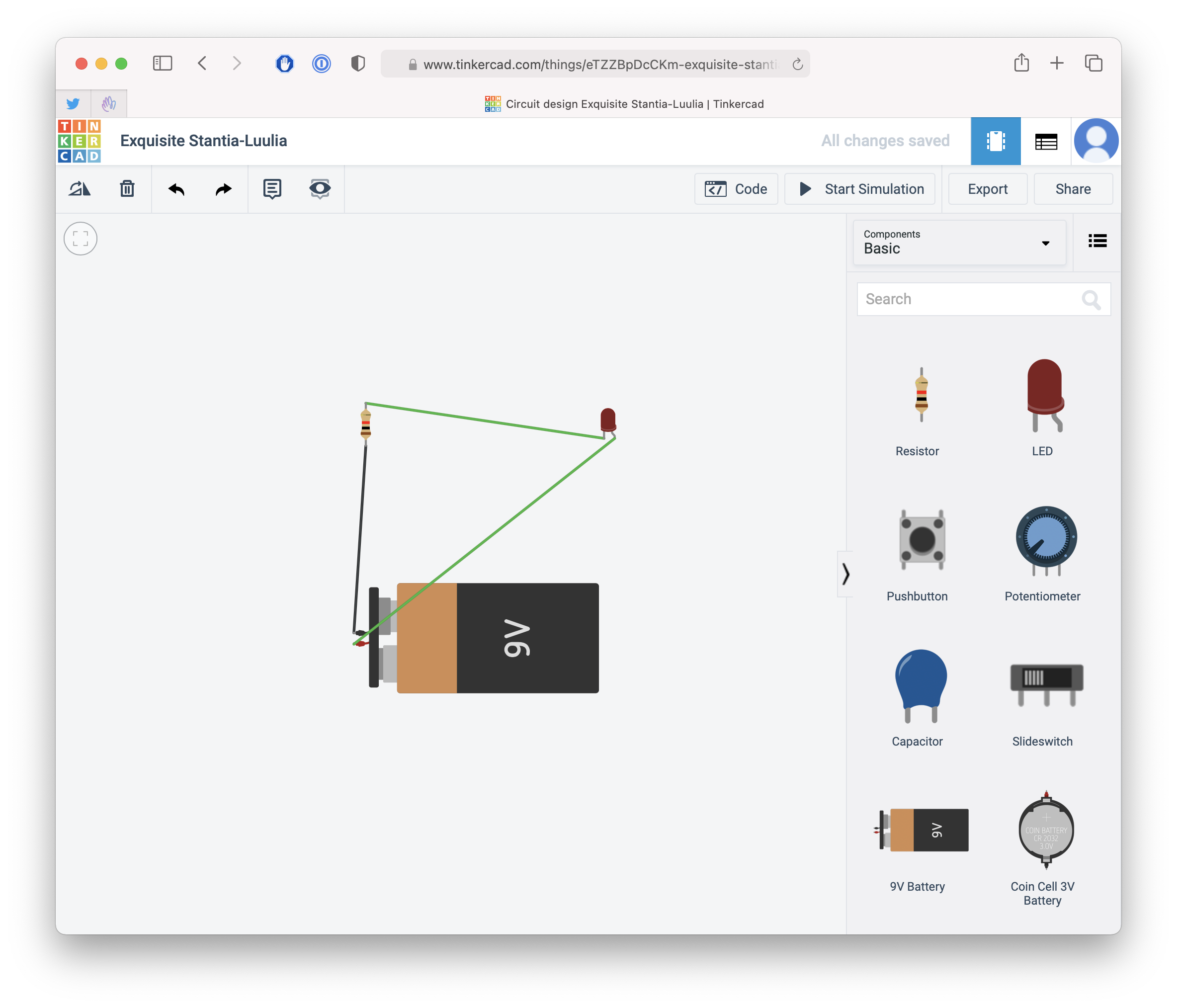
Pick a 9V voltage battery, a resistor and a LED:
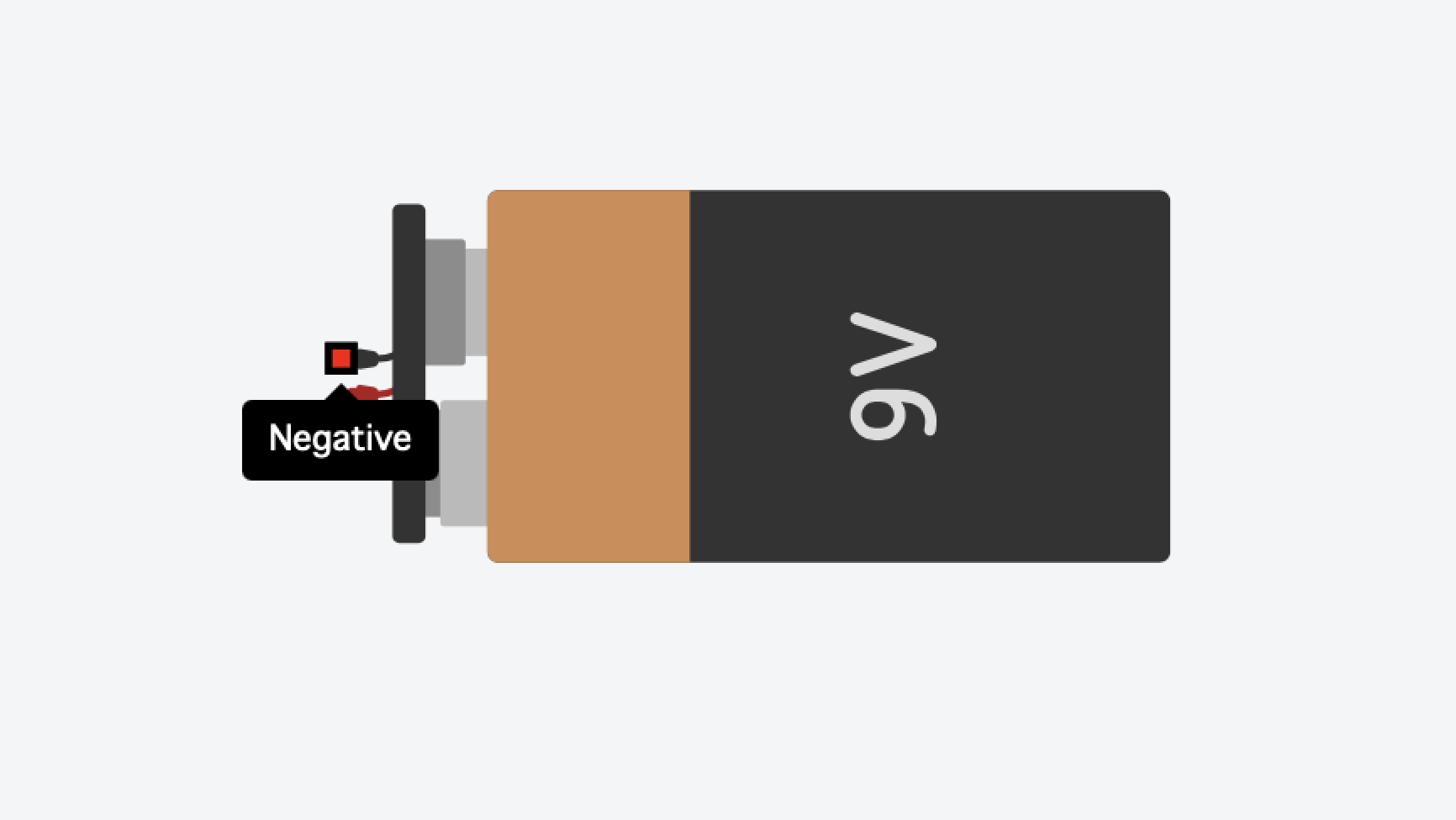
Now hovering each item will show you the connections you can create from them, or to them. For example the battery has a positive pole and a negative pole:
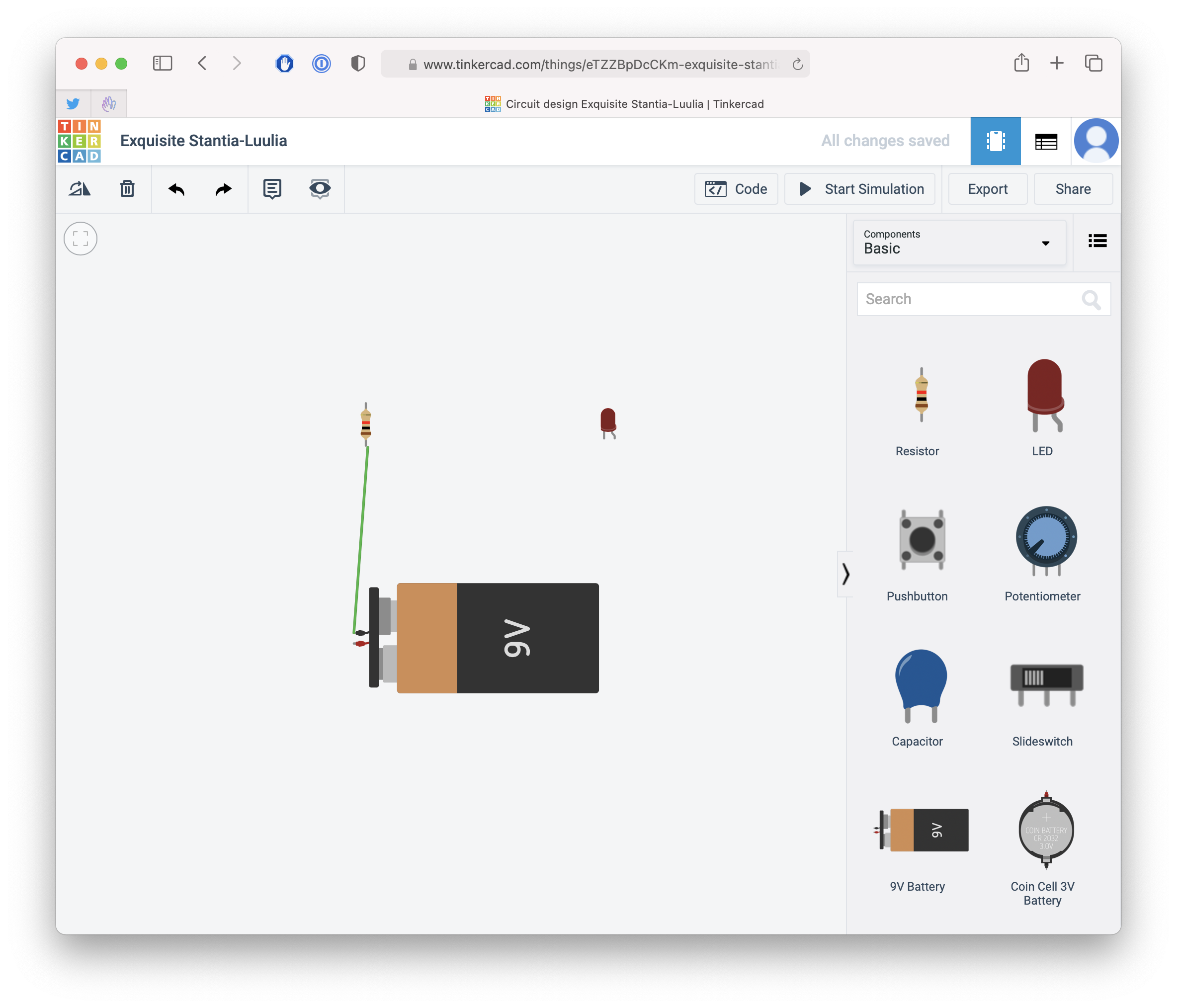
Drag the negative pole to one of the poles of the resistor:
Now connect the resistor to the pole of the LED called cathode, the one that’s straight, on the left.
Finally, connect the anode, the right pin of the LED, to the positive pole of the battery:
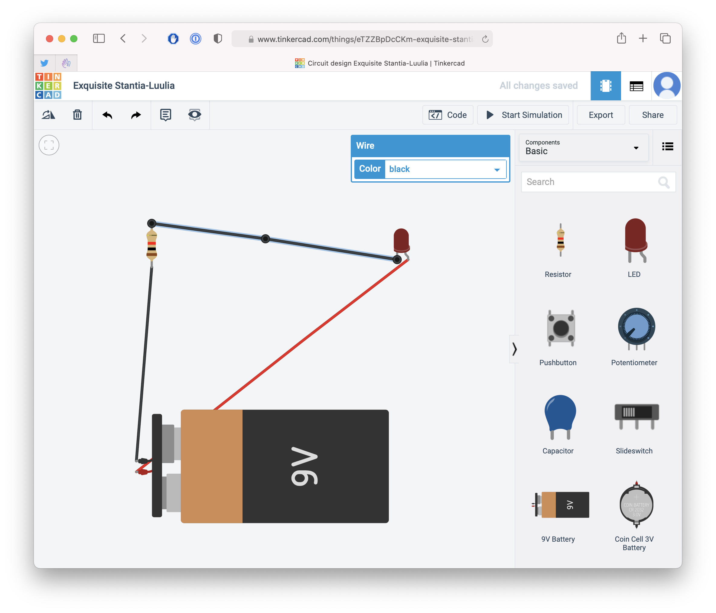
You can change the colors of the wires clicking on them:
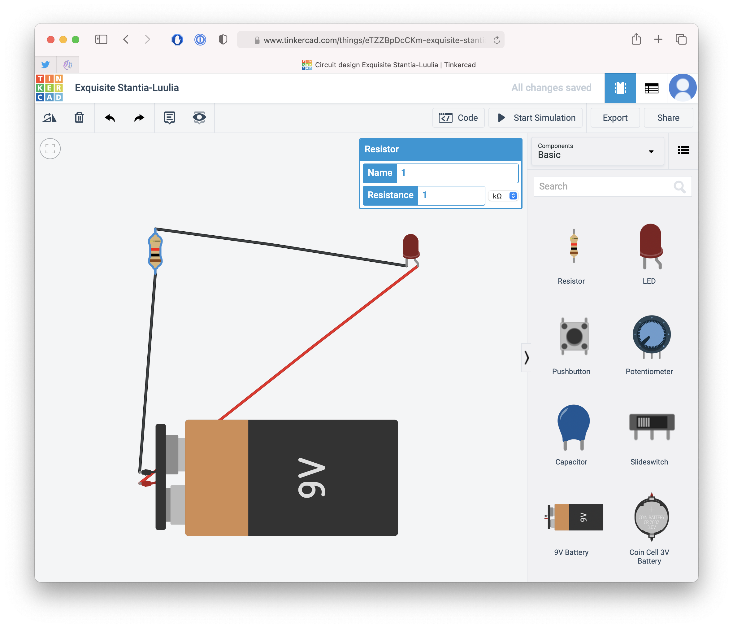
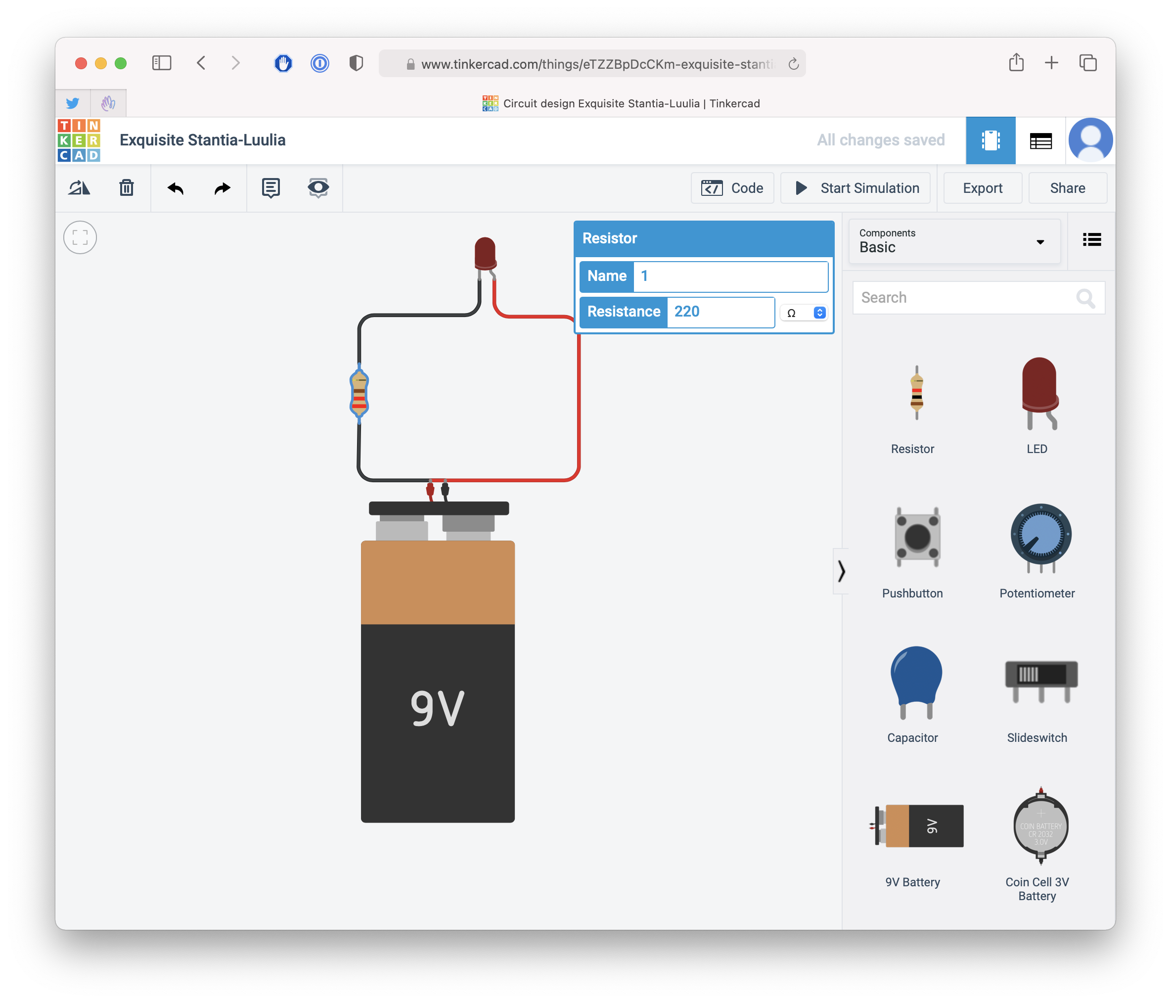
And you can alter the settings for each component by clicking on it. For example, click the resistor to find out and change its resistance value, which by default is 1kΩ:
Double-click a wire to add a point to it, so you can make a nicer circuit:
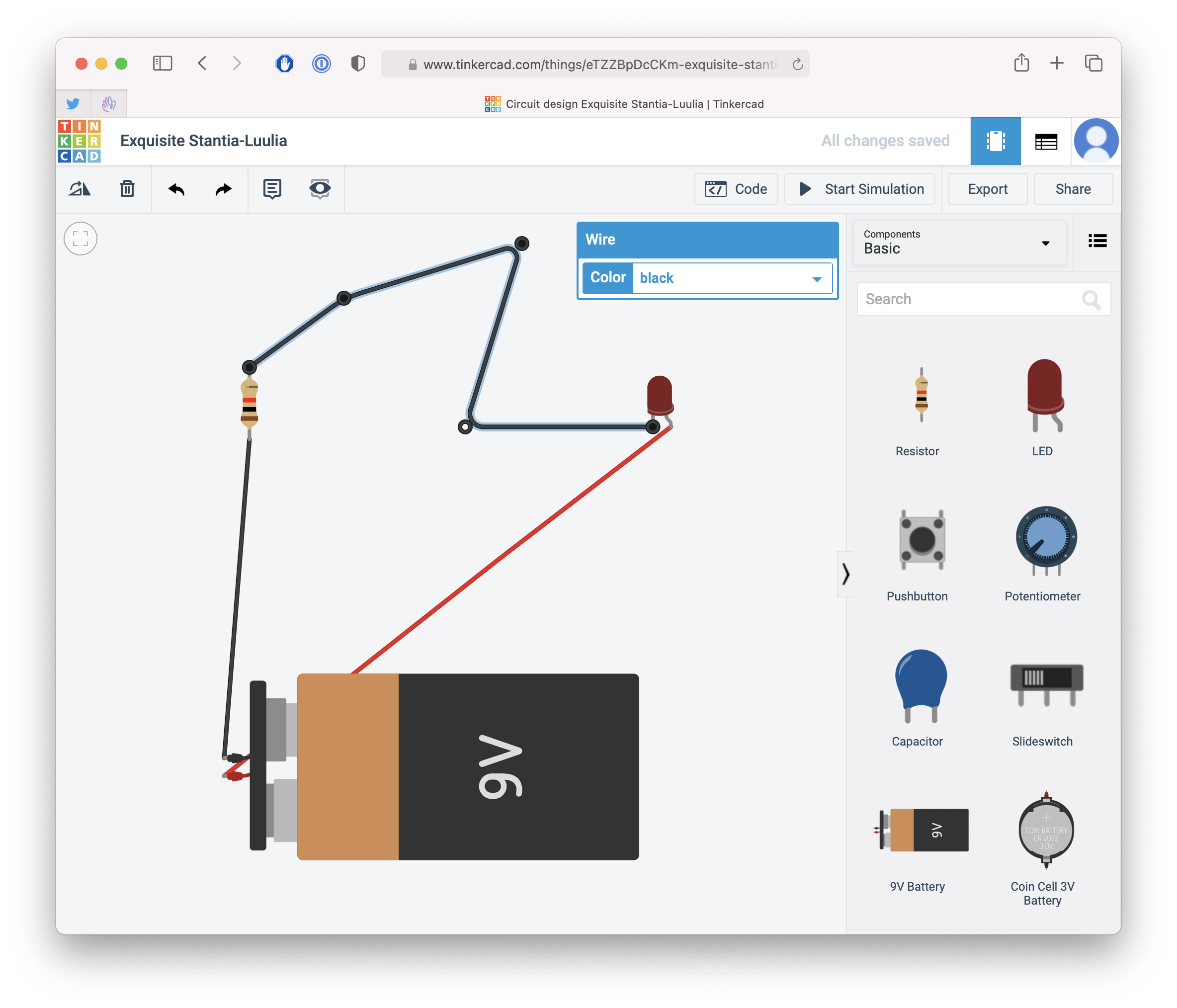
After a little tidying up, here’s the result:
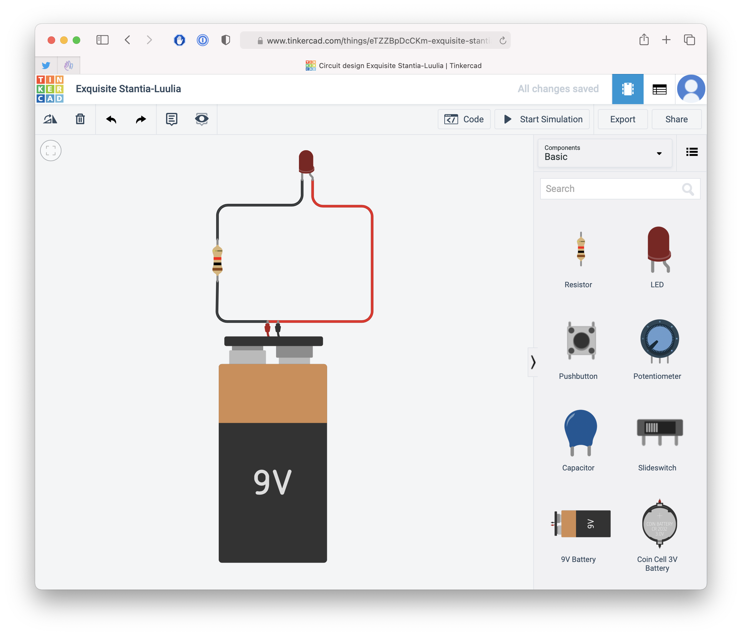
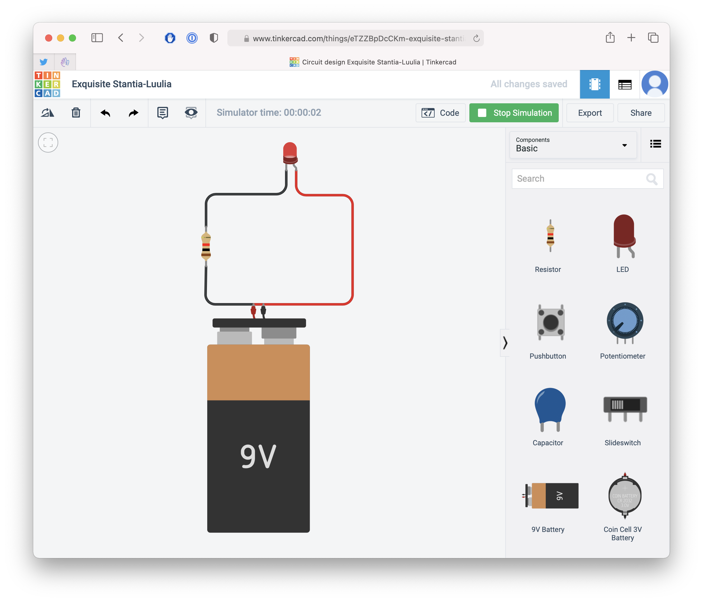
Now click the Start simulation button. You will see the LED light up, until you click Stop simulation:
Now try changing the resistance to 220Ω:
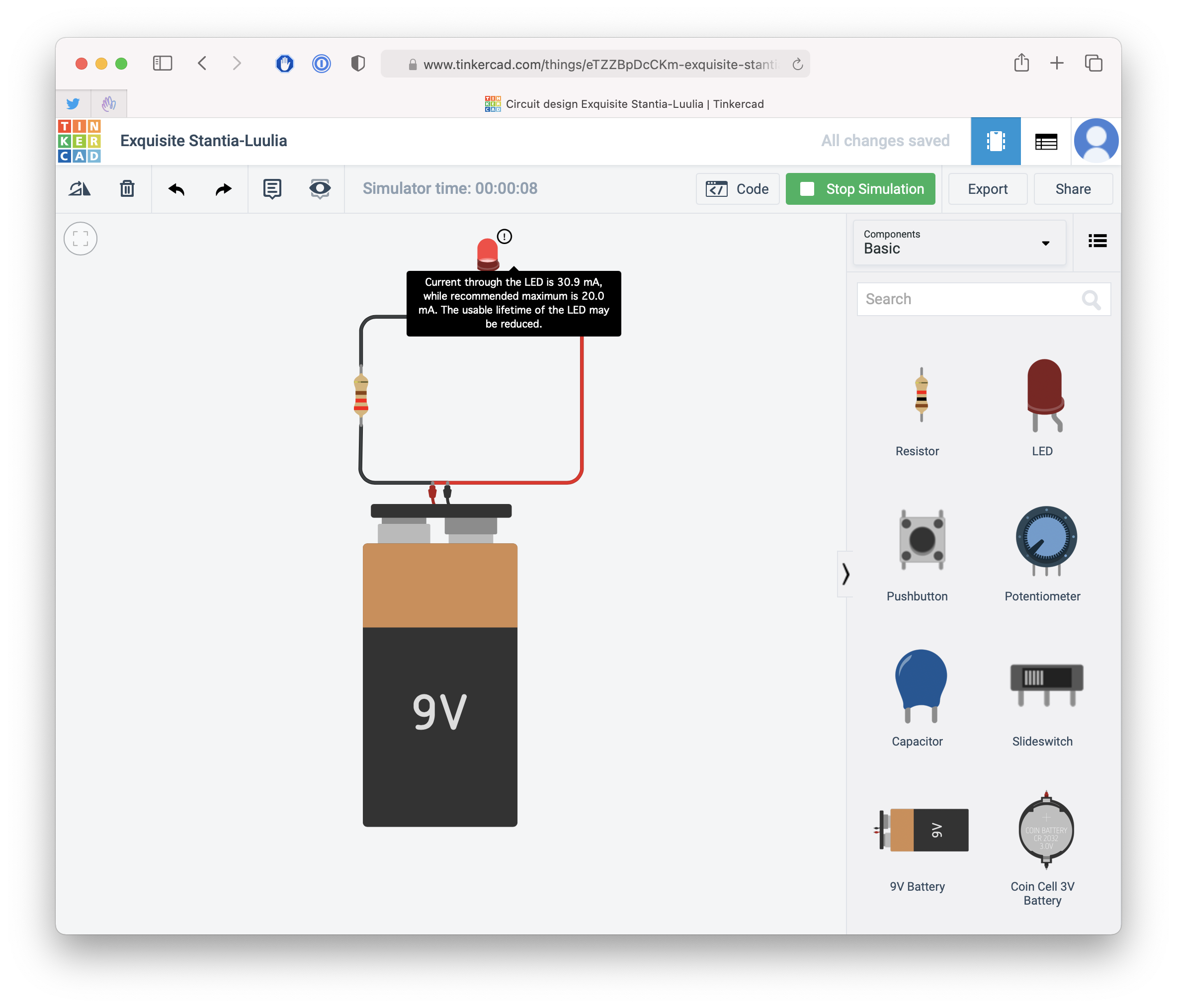
Run the simulation again, and you will see a warning on the LED, informing you the current flowing through is too much, and 20mA is the recommended maximum amount of current the LED can handle:
You can also change the value of the resistor while the simulation is running. If you write 1000Ω instead of 220, you will see the light on the led will be less bright.
Add 10000Ω, and the LED will now show any light at all.
The higher the resistance of the resistor, the less current is flowing in the circuit, and as such the less current can be consumed by the LED to show a bright light.
Remember Ohm’s law, I = V / R: the current flowing through the circuit with a 220Ω resistor is 9 / 220 = 40mA.
With a 1kΩ resistor the current is 9/1000 = 9mA.
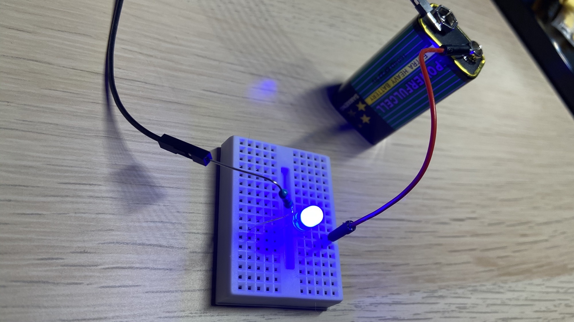
Here is the same circuit, but in the real world:
Related posts about electronics: