Electronic components: Analog Joystick
By Flavio Copes
Learn how the analog joystick works with Arduino: read its VRx and VRy axes with analogRead from 0 to 1023, and detect clicks through the SW switch pin.
The analog joystick is one of those electronic components you have certainly used while playing video games:
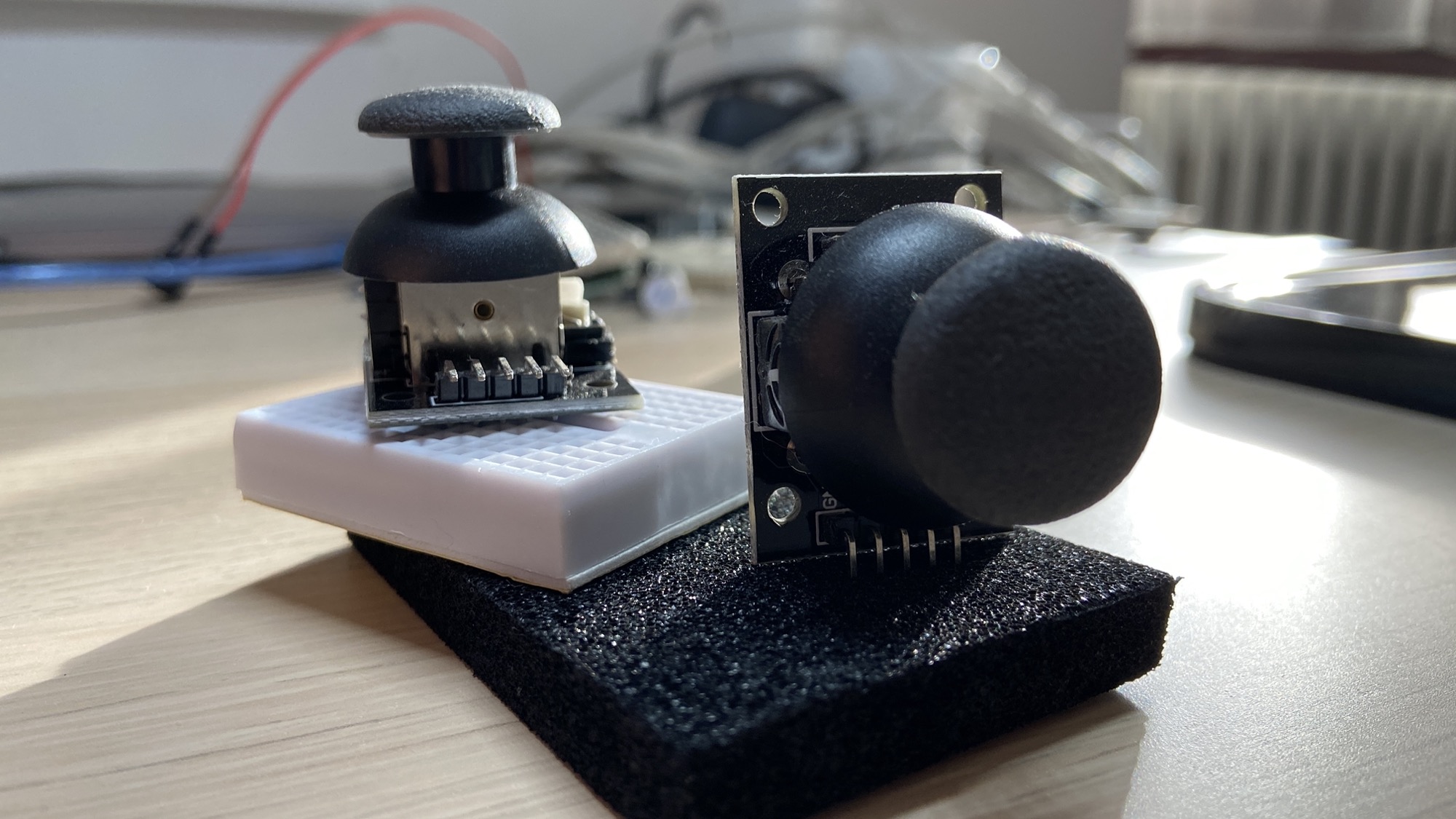
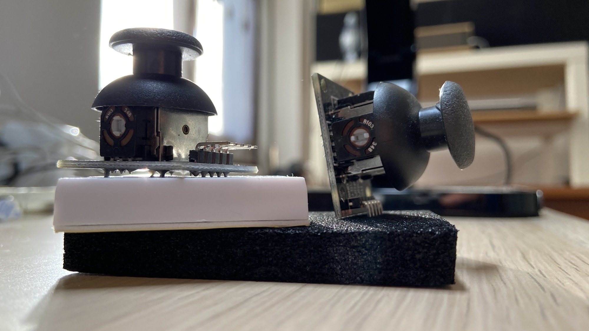
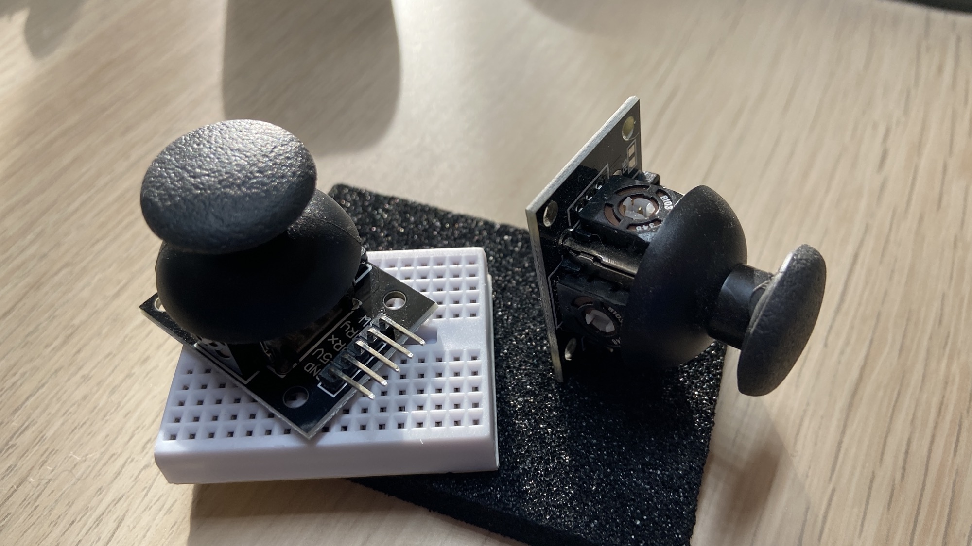
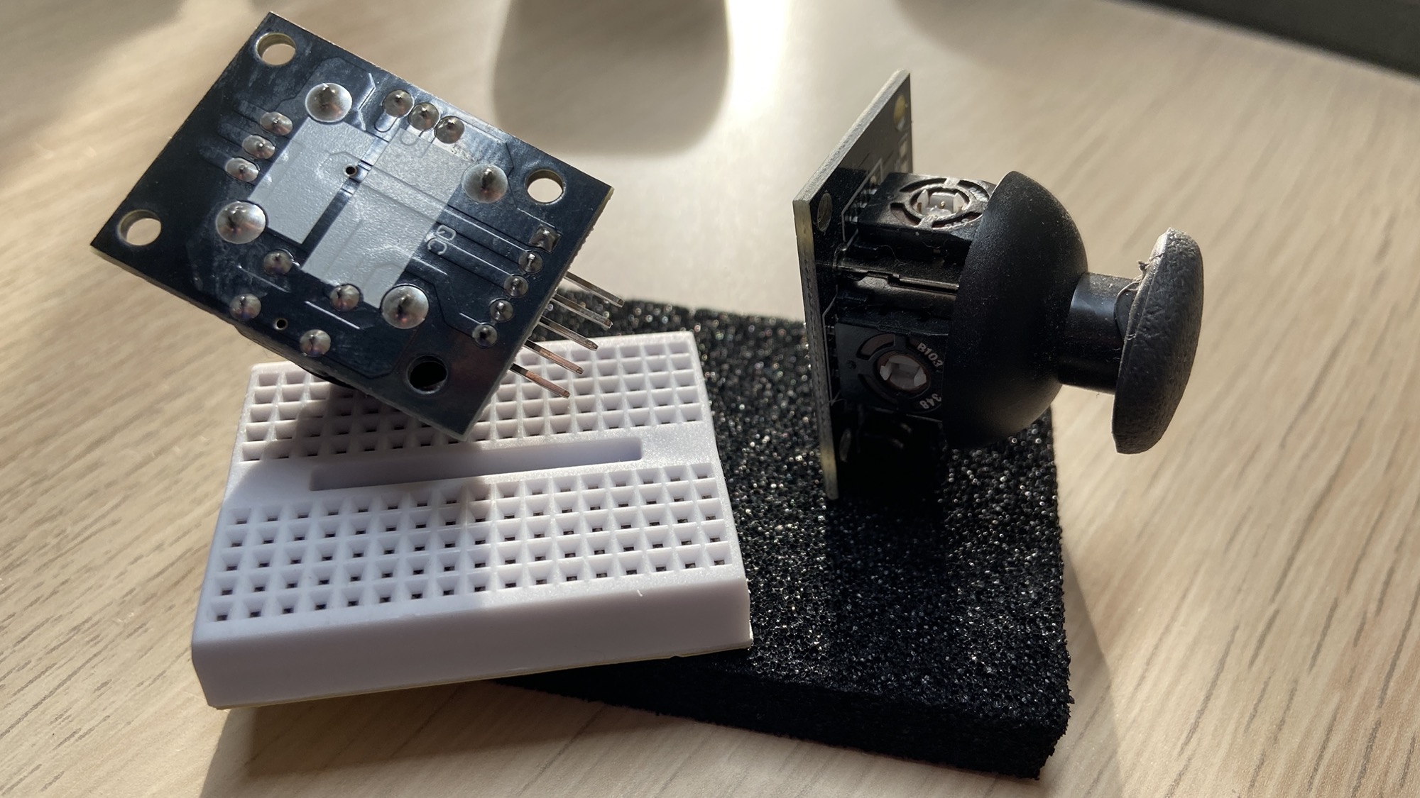
You can move the joystick around, and you can also click it from top to bottom:
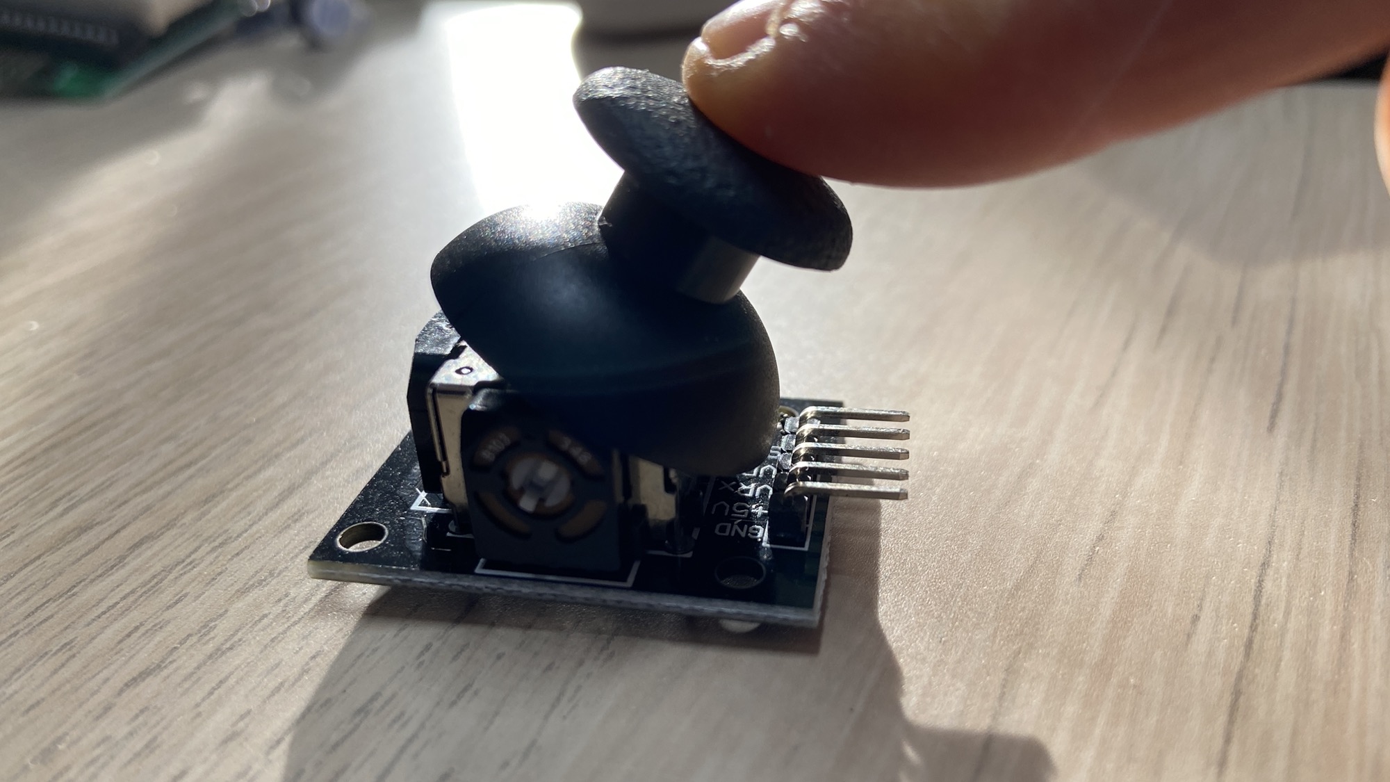
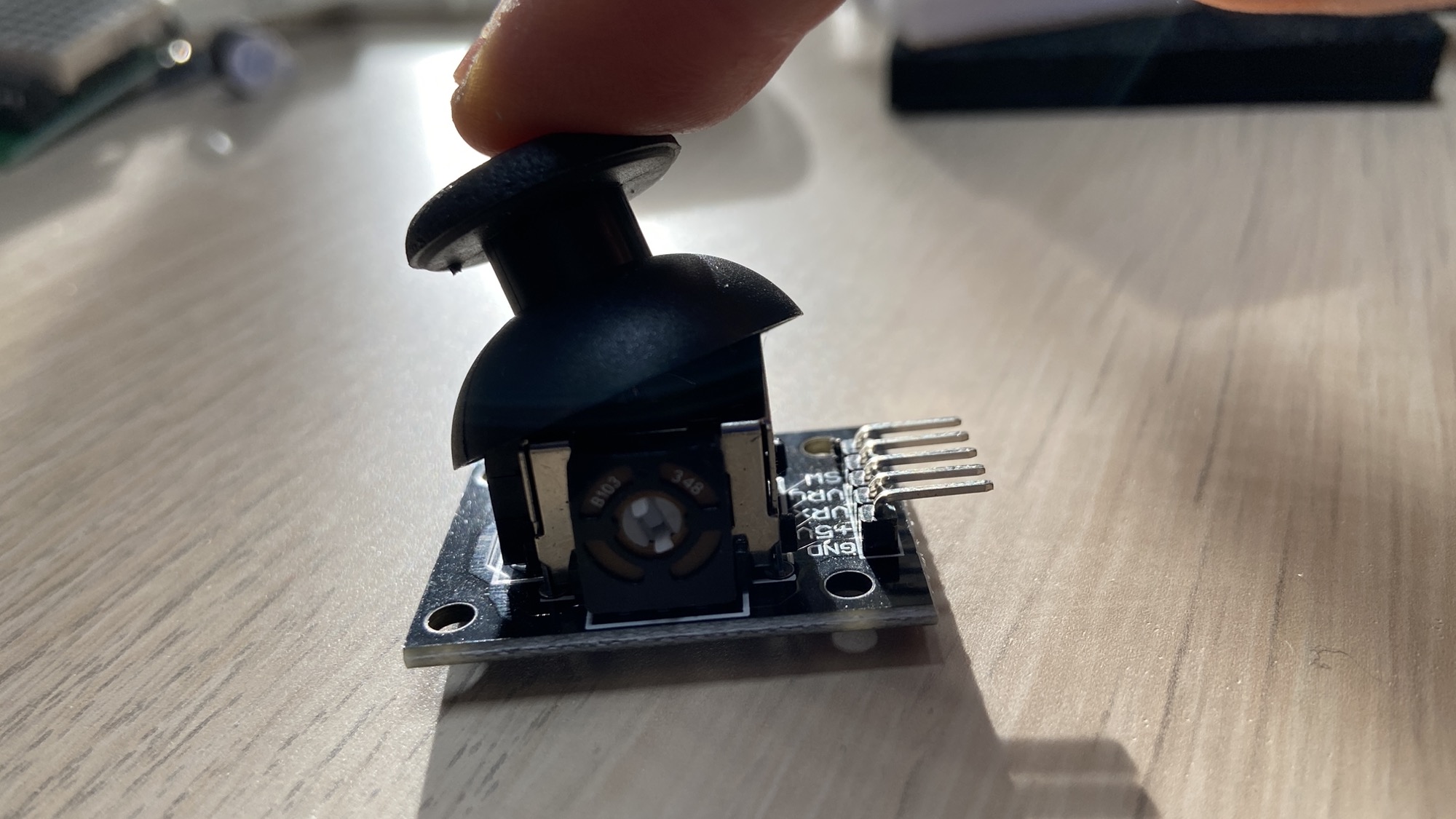
Any action performed will send the appropriate electronic signals to the circuit it’s connected to.
The 5 pins of the joystick are:
GND, the input LOW signal+5V, the input HIGH signal, can also be 3.3V when using a 3.3V based deviceVRx, the analog signal that represents the position of the joystick on thexaxisVRy, the analog signal that represents the position of the joystick on theyaxisSW, short for switch, is the digital valueLOWwhen pressed, otherwiseHIGH
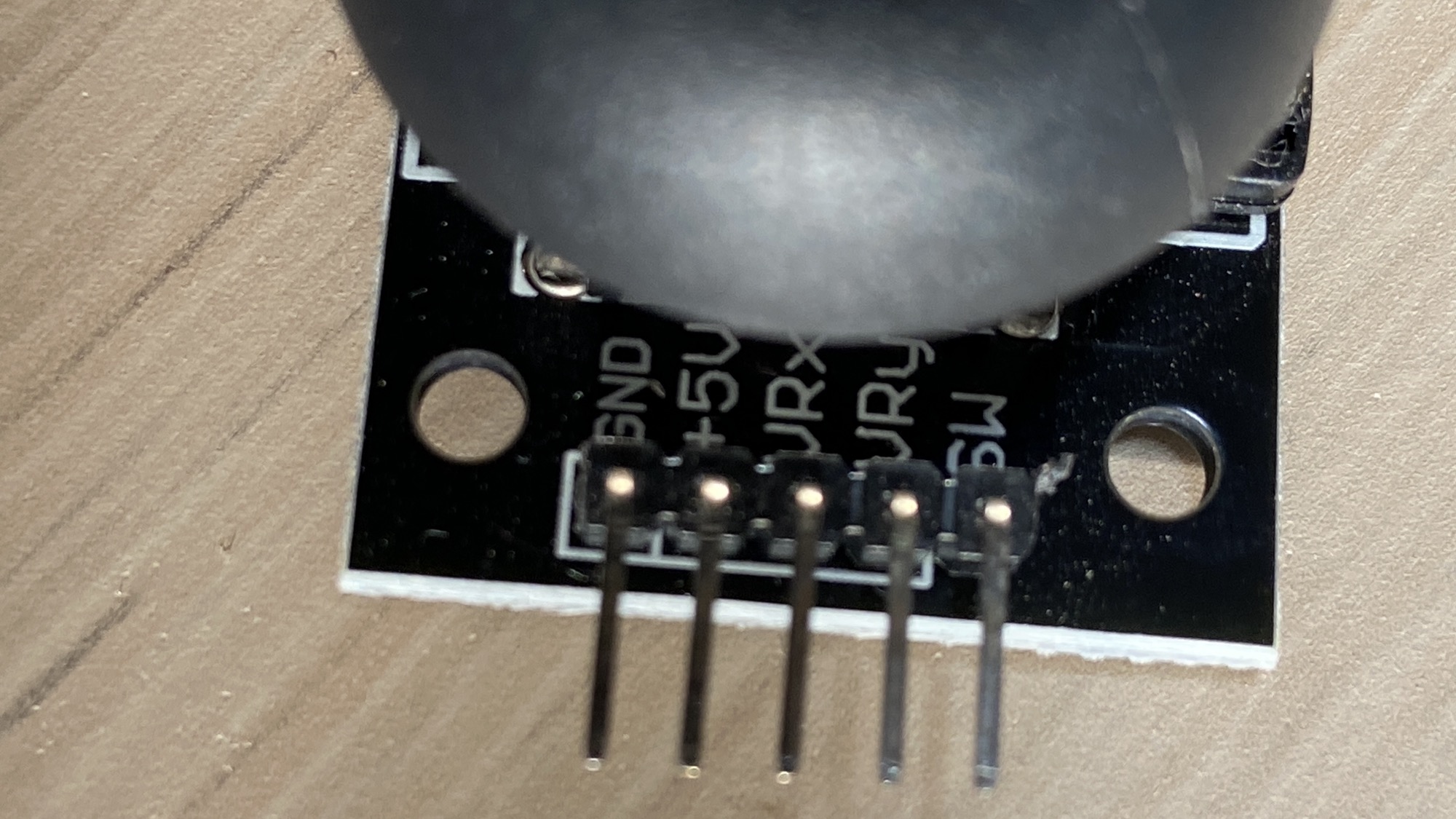
You connect VRx and VRy to an analog input pin to get their value.
Analog inputs range from 0 to 1023 since they use a 10 bits resolution.
When watching the joystick with the pins on the left, the X axis values assumes values from 0 (full left) to 1023 (full right) and 498 in the middle. The Y axis values assumes values from 0 (top) to 1023 (bottom) and 498 in the middle.
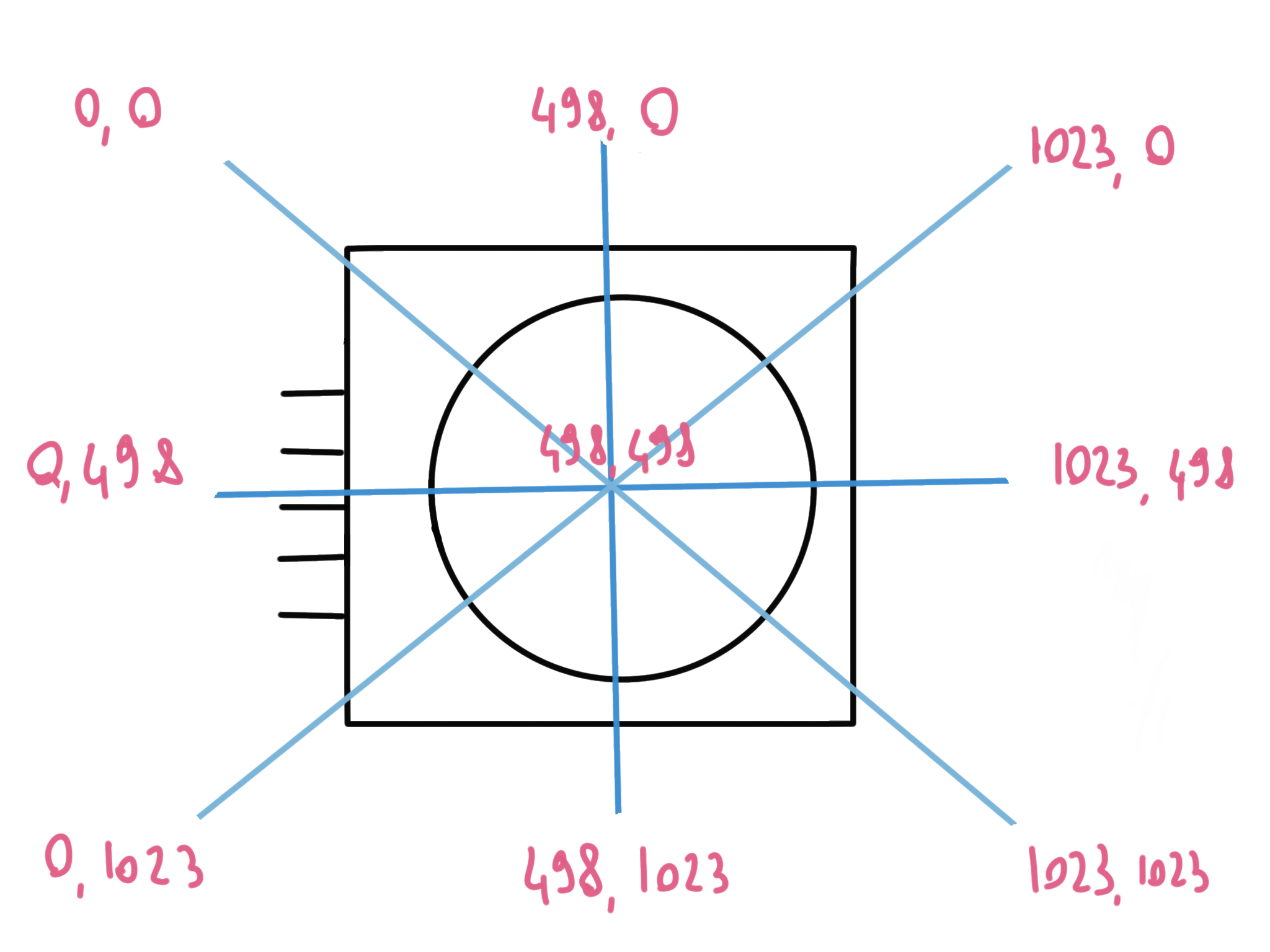
Assuming VRx is connected to A0 and VRy to A1:
int x = analogRead(A0);
int y = analogRead(A1);
A simple program that prints the values is this:
void setup() {
  Serial.begin(9600);
}

void loop() {
  int x = analogRead(A0);
  int y = analogRead(A1);
  Serial.print("X = ");
  Serial.print(x);
  Serial.print("\tY = ");
  Serial.println(y);
  delay(100);
}
You can also think of them as voltage values. Assuming a 5V positive voltage, you can multiply the value you get by 5.0, and then divide it by 1023 to get a 0 to 5 range:
x = analogRead(A0);
y = analogRead(A1);

float x_val = (x * 5.0) / 1023;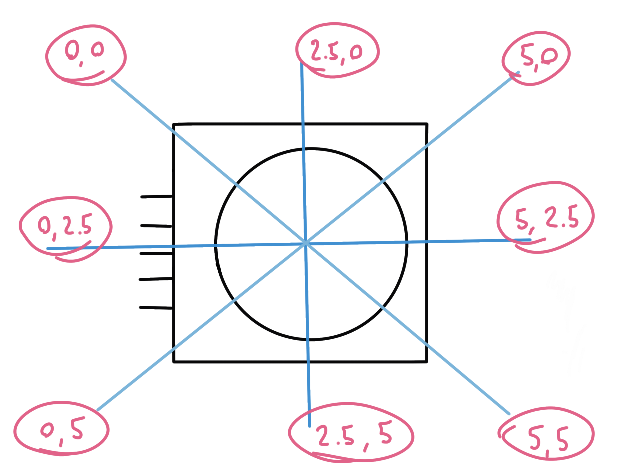
You can perform a similar calculation to get the values relative to a 3.3V Vcc.
Want me to talk about your product? You can sponsor this site.
Related posts about electronics: